Topics:
- Series and parallel circuits in general
- Series circuit in practice
- Series circuit: calculating equivalent resistance
- Series circuit: calculating current and partial voltages
- Parallel circuit: calculating equivalent resistance
- Parallel circuit: calculating partial currents
- Combined circuit
- Combined circuit exercise
Series and parallel circuits in general:
On this page we look at series circuits, parallel circuits and combined circuits that are used in automotive technology. Knowledge of the basic electronics is required for this.
Series circuit:
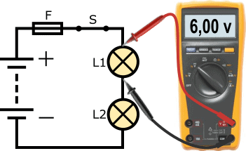
The following circuit shows a circuit with a 12-volt battery, a fuse (F), closed switch (S) and two bulbs (L1 and L2). The ground wire of bulb L1 is connected to the positive wire of bulb L2. We call this a series circuit.
The current through both bulbs is the same. The voltage is divided. Because in this example two bulbs with the same power rating are used, the battery voltage of 12 volts is divided into 6 volts per bulb. For that reason, bulbs in automotive technology are not placed in series. In addition, if one bulb is defective, the entire circuit is interrupted, causing the other bulb to go out as well.
Parallel circuit:
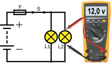
In automotive technology we are almost always dealing with parallel circuits. The following circuit shows the circuit in which bulbs L1 and L2 both have their own positive and ground wire. The voltage across each load is equal to the battery voltage; this can be seen in the voltmeter reading. In this example the same bulbs are used as in the series circuit; however, here they light more brightly because the bulbs now receive more voltage and current.
Another characteristic of a parallel circuit is that when one bulb is defective, this has no effect on the operation of the other bulb.
Series circuit in practice:
As described in the previous paragraph, in automotive technology we are almost always dealing with loads connected in parallel. After all, we want as much voltage and current as possible to make the loads operate, and as little risk of malfunctions as possible if one of the loads fails.
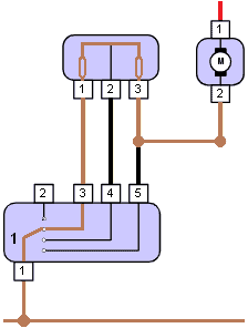
In practice we do find loads that are placed in series in order to perform their task. As an example we take the interior fan / heater motor. To be able to control the speed of the fan, a resistor is placed in series in the ground connection between the electric motor and the ground point. We also call this a series resistor (ballast resistor).
By placing one or more resistors in series, the loss increases and the voltage across the electric motor decreases.
Read more about this on the page: series resistor of the interior fan.
An unwanted series circuit can also be present; for example a contact resistance in a positive or ground connection resulting in a voltage drop (see the page “measuring with the multimeter“).
Series circuit: calculating equivalent resistance:
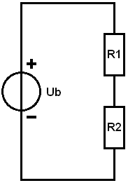
Every electrical load has an internal resistance. A high resistance results in a low current; in other words: the resistance determines the current. The applied voltage is equal to the source voltage (Ub, i.e. the battery voltage).
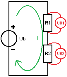
In the example the loads (R1 and R2) are connected in series. The negative of R1 is connected to the positive of R2. The current through the resistors is the same. To be able to calculate the current and finally the partial voltages with Ohm’s Law, we can start by calculating the equivalent resistance. The resistance values are as follows:
- R1 = 15 Ω
- R2 = 10 Ω
To calculate the equivalent resistance, we replace the resistors R1 and R2 in the diagram with Rv.
In a series circuit we can add up the resistance values. The formula and calculation are shown below.
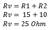

The result of the calculation shows us that the equivalent resistance is 25 Ohms. In the following examples we can continue calculating with Rv.
Series circuit: calculating current and partial voltages:
In this paragraph we calculate the total current and the partial voltages across the resistors R1 and R2. To do this we first need a source voltage (Ub). In this calculation example this voltage is 14 volts.
With a known source voltage (Ub) and equivalent resistance (Rv) we can calculate the total current (I). We determine I using Ohm’s Law:
The current in a series circuit is the same through each resistor. The green arrow in the image indicates the direction of current. The current is 560 milliamps.
Now that the current is known, we can calculate the partial voltages. This allows us to determine how much voltage each resistor “uses”.
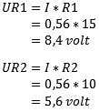
- The voltage (U) across resistor R1 is indicated as: UR1. Using Ohm’s Law we multiply the current by the resistance value. The voltage across the resistor is 8.4 volts.
- We calculate UR2 using the same current, but now with the resistance value of R2; this voltage is 5.6 volts.
As a check you can add the partial voltages together and compare them with the source voltage. We add UR1 and UR2 together: this is 14 volts. That is equal to the source voltage. If you arrive at a different answer, in the case of a small deviation this may be due to intermediate rounding, or an error in the calculation.
Parallel circuit: calculating equivalent resistance:
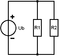
In this example R1 and R2 are connected in parallel to each other. Now the negative of one load is no longer connected to the positive of the other. The voltage across the resistors is now equal to the battery voltage. The current is divided over the resistors. With equal resistance values the total current (I total, abbreviated as It) is divided by two. To calculate It we first have to determine the equivalent resistance. Again we replace R1 and R2 with one resistor, called Rv. We then get the same situation as in the example with the series circuit. The resistance values are:
- R1 = 10 Ω
- R2 = 20 Ω
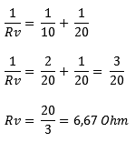
In a parallel circuit we cannot simply add the resistance values. The general formula is:
We fill in the resistance values of R1 and R2:
Method 1: We calculate the result of one tenth and one twentieth and add the values together.
Method 2: Another way is to calculate the equivalent resistance in fractional form. Again we substitute the values of R1 and R2 into the equation. Under the fraction bars (the denominators) are unequal numbers; we cannot add the denominators together. We therefore first make them the same. In this example it is easy: one tenth fits twice into one twentieth, so we multiply one tenth in its entirety by 2. We then get two twentieths. In proportion this is the same as one tenth. With equal denominators we can add the fractions: this results in three twentieths. To calculate the equivalent resistance we have to invert the fraction: 1/RV becomes RV/1 (we can then cross out /1) and three twentieths becomes 20 divided by 3. The result of 6.67 Ohms is equal to the result with method 1.
Parallel circuit: calculating partial currents:
We can calculate the total current (It) by dividing Ub by Rv:
The current Itotal will be divided into I1 and I2. Through R1 a different current flows than through R2. At the junction the partial currents come together again and It flows back to the negative terminal of the battery.
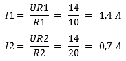
For a parallel circuit the following applies: the voltage across each load is equal to the source voltage:
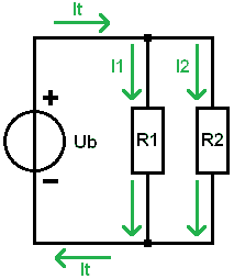
So in the formulas for UR1 and UR2 we enter the same value as the battery voltage: in this case 14 volts. We divide the voltage by the resistance values and obtain the partial currents. Through resistor R1 a current of 1.4 amps flows and through R2 700 milliamps.
When we add the two partial currents together, we again obtain the total current of 2.1 amps.
Combined circuit:
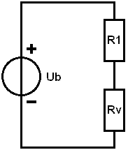
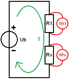
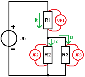
In a combined circuit we are dealing with a series and a parallel circuit in one circuit. In the image we see that resistor R1 is in series with the resistors R2 and R3 which are connected in parallel. In practice we could encounter this with a poor positive wire to two bulbs: R1 is then the contact resistance, R2 and R3 are the bulbs.
We are going to calculate the currents and voltages and we assume the following data:
- Ub = 12 volts;
- R1 = 0.5 Ω
- R2 = 15 Ω
- R3 = 15 Ω
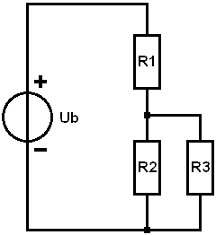
From a parallel circuit we know that the voltage across the resistors is equal to the source voltage. Because we are now dealing with a combined circuit, this no longer applies; part of it is taken up by R1. However, the voltages across R2 and R3 are equal to each other.
For clarity we divide the calculations into 5 steps.
1. Determine Rv of the parallel circuit:
We replace R2 and R3 with Rv and, for convenience, calculate Rv in fractional form.
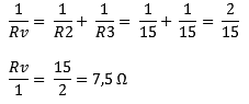
We now have a series circuit: R1 obviously remains 0.5 Ω and Rv is now 7.5 Ω
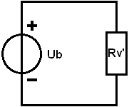
2. Determine Rv of the series circuit:
In step 1 the equivalent resistance of R2 and R3 was determined. The equivalent resistance was in series with resistor R1.
In this step we add the resistance values of R1 and Rv together to again calculate the equivalent resistance, but now that of the series circuit. We call this equivalent resistance Rv’ (with an accent) because it is a “second” Rv in the circuit.
3. Calculate Itotal:
The total current is 1.5 A and flows through resistor R1 and the equivalent resistance Rv’.
4. Calculate the partial voltages:
We rebuild the diagram step by step; we place R1 and Rv in series to use the total current and resistance values to calculate the partial voltages UR1 and URv.
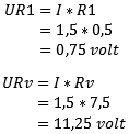
As a check: the sum of the partial voltages corresponds to the supply voltage: (UR1 + URv = Ub), so up to now no calculation errors have been made.
5. Calculate the currents:
We complete the circuit again. In step 4 we determined that the voltage across resistor R1 is 0.75 volts. The voltage across the equivalent resistance Rv is 11.25 volts. Because in a parallel circuit the voltages across the loads are equal, we know that the voltage across both R2 and R3 is 11.25 volts.
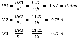
From the calculation results it can be seen that the total current flows through R1, and then the current is divided between R2 and R3. With unequal resistance values these currents differ from each other.
Combined circuit exercise:
In this paragraph you can practice calculating with the combined circuit yourself. To make it easy for yourself you can follow steps 1 through 5 from the previous paragraph. Extend the step-by-step plan with step 6 to calculate the partial voltages of R4 and R5.
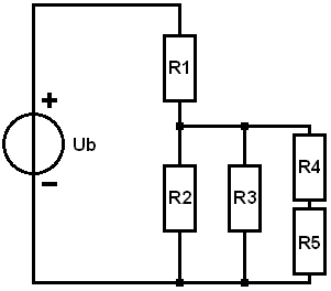
Given:
- Ub = 10 volts
- R1 = 1 Ω
- R2 = 10 Ω
- R3 = 4 Ω
- R4 = 5 Ω
- R5 = 15 Ω
Required:
- All partial voltages (UR1 to UR5)
- All branch currents.