Measuring voltage:
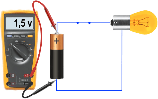
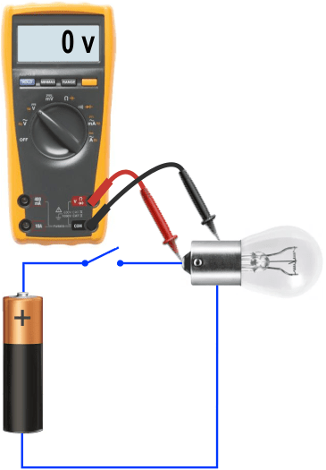
With a multimeter we can measure the voltage (volt) across electrical components such as the battery, wiring, switch, and lamp. We then also call it a “voltmeter”. We connect the multimeter in parallel with the circuit and set it as follows:
- Set the rotary switch to V for volt (voltage);
- In this case we choose direct current (DC);
- Red test lead in the V socket;
- Black test lead in the COM socket.
The red test lead is the positive lead and the black is the negative lead. The test probes are located at the end of the test leads. We hold the red probe against the positive terminal of the battery and the black probe against the negative terminal. In this way we measure the voltage difference in the battery. We read this voltage from the display and it is 1.5 volts.
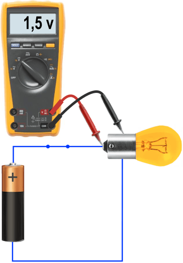
The battery voltage of 1.5 volts is conducted via the positive wire to the positive terminal of the lamp when the switch is closed. With the multimeter we measure the voltage difference across the lamp: the bottom point is positive and the housing is ground. We hold the probes against the positive terminal and ground to measure the voltage difference across the lamp.
When the switch is opened, the circuit is interrupted. No more current flows through the circuit, causing the lamp to go out. With this differential measurement, the multimeter indicates 0 volts. The switch is on the positive side of the lamp, which means the lamp is de-energized. Later on in another paragraph we will go into more detail on positive-switched and ground-switched lamps and the associated differential measurements.
Measuring current:
With the multimeter we can determine how much current flows through a circuit. It is important that the multimeter must be connected in series. The current then flows through the multimeter. We then call it an “ammeter”. We set it as follows:
- Set the rotary switch to A for ampere;
- With this type of multimeter, every time the A setting is selected, the yellow button must be pressed to switch from AC to DC;
- Red test lead in the 10A socket;
- Black test lead in the COM socket.
To place the multimeter in series, the circuit must be interrupted somewhere. We can do this by removing the fuse or opening the switch. Where the circuit is interrupted, you connect the probes. The two images below show the current measurement with the switch opened. The measurement is taken in ampere and in milliampere. More explanation about this follows below the images.
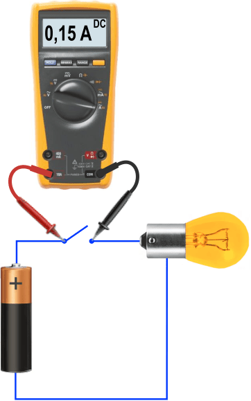

As we can see in the images, the current can be measured in two settings.
- The first measurement is in the ampere setting. In this position, currents up to a maximum of 10 amperes can be measured;
- The second measurement is in the milliampere setting. In this position, currents up to a maximum of 400 milliamperes can be measured. This is equal to 0.4 A.
If you are not yet able to estimate how much current flows through a circuit, it is wise to first measure in the 10A setting. If the current is less than 0.4 A, you can decide to insert the test lead into the mA socket and set the rotary switch to mA. Do not forget to press the yellow button to switch from AC to DC. The measured value is the same, but in the mA setting it is more accurate.
- 0.15 A is equal to 150 mA;
- 147 mA is therefore 0.147 A (this setting is more accurate).
Mistakes are regularly made when measuring current. The most common mistakes are shown in the next two images.

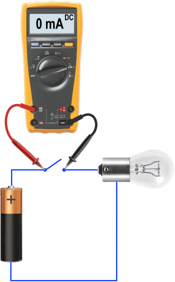
When we take a measurement in which the load is functioning properly—in this case the lit lamp—but the multimeter indicates 0 A, then the meter is still set to AC, or the circuit is not interrupted. The current follows the path of least resistance, which is through the closed switch. In effect, the multimeter is now connected in parallel with the circuit. Nothing will be damaged because of this. As soon as the switch is opened, the correct value appears in the display.
If the current has risen above the rating of the fuse, the fuse will blow in order to protect the electronics in the multimeter. In the mA setting this is 400 mA. You will notice this when the meter is connected correctly, but the load remains off and the meter indicates 0 mA or 0 A. In this case we can choose to perform the measurement in A, since this setting is protected up to 10 A and the chance that the fuse is defective or will blow is smaller.
Measuring resistance:
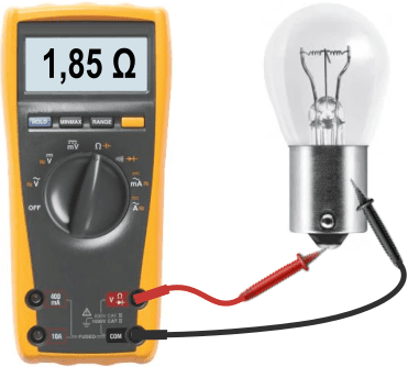
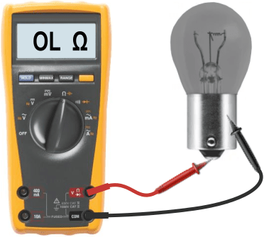
The third measurement we can perform with the multimeter is the resistance measurement. With this we can check electrical components for internal short circuits or interruptions. In the images below, two measurements are shown in which the resistance of the lamp is determined. The multimeter now functions as an “ohmmeter” and is set as follows:
- The rotary switch is set to the Ω (ohm) position for the resistance measurement;
- The red test lead is inserted into the Ω socket, which is also the same socket we use for the voltage measurement;
- The black test lead is again inserted into the COM socket.
The resistance of the lamp is 1.85 ohms. This indicates that the lamp is in good condition. Note: when the lamp is lit, the resistance changes due to the temperature. While it is lit we cannot measure the resistance, but immediately after switching off, the measured value will be considerably lower.
A lamp ages as it burns many hours. The tungsten filament becomes thinner and evaporates onto the inside of the glass. We can see this because the lamp becomes darker. A dark-colored lamp will fail within a short period of time. In the second measurement this has happened: the tungsten filament has broken and the lamp no longer works. The circuit is therefore interrupted. Because the connection is broken, the resistance has become “infinitely” high. In that case the multimeter indicates OL. Some multimeters then display “1.”
With the ohmmeter we can perform the following measurements:
- the internal resistance of electrical and non-electrical components;
- locating interruptions in an electrical circuit, such as in circuit boards or in wiring;
- locating electrical connections by means of the continuity (beep) setting;
- locating a ground connection;
- checking whether the test leads are in good condition.
The last measurement is crucial when making a diagnosis. When a test lead is in poor condition, it affects every voltage or current measurement with the multimeter or oscilloscope (the latter can only measure voltage).
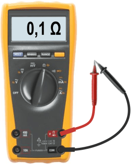
If a test cable has been pinched at some point, or has been bent a lot and pulled on through intensive use, the connection may drop out when it is held at a certain angle. This can easily be checked by holding the ends of the probes together: the resistance is then approximately 0.1 ohm. If the resistance is many times higher, or OL, then the test leads are no longer usable.
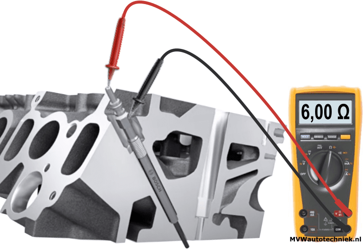
Another example of a resistance measurement is measuring the glow plug that we find in a diesel engine.
- A good glow plug has a resistance of about 6 ohms.
- If the glow plug is open-circuit, the resistance is infinitely high.
- In the event of an internal short circuit (the coil and housing make internal contact), we measure (theoretically) a resistance of 0 Ω and in reality a resistance of 0.1 Ω due to the “always present” resistance in the test leads, as described in the previous paragraph on checking the test leads.
See the page about the glow plug for more information about operation and measurement techniques.
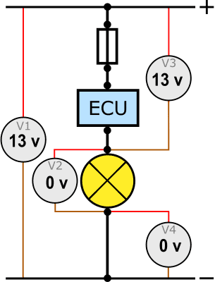
V4 measurement:
On this website, the voltage levels, signal transmission and measurement methods of many types of sensors, actuators, ECUs and networks are described. These can be found on the pages themselves, such as those about the temperature sensor, passive, active and intelligent sensors, relays and CAN bus. On these pages, the measurements are specifically about that subject.
When troubleshooting we use the voltmeter in most cases and sometimes the current clamp. We hardly ever perform current and resistance measurements during diagnostics:
- To measure the current, the circuit must be interrupted (undesirable), and the magnitude of the current says too little about possible losses. After all, the current strength is the same throughout the entire circuit. The ammeter is also limited to 10 A. It may sometimes be desirable to use a current clamp that is not limited to a specific current strength.
- Measuring resistance is only advisable when determining whether there is a connection or an interruption. In all other cases, we measure an “unloaded” resistance and the resistance value is unreliable.
The above boils down to the fact that we almost always use the voltmeter in our diagnostics. For complex diagnostics, we use an oscilloscope, which is also a (graphical) voltmeter. With the voltmeter we measure voltage differences and voltage drops under load, i.e. when the consumer is operating. This makes the measured value the most useful.
To provide guidance for measurements with the voltmeter, it is useful to master the V4 measurement. By means of four voltage measurements one can “roughly” find the cause of a poorly or non-functioning consumer. This paragraph explains how to perform the V4 measurement, which values you can expect and how to recognize when there is a fault.
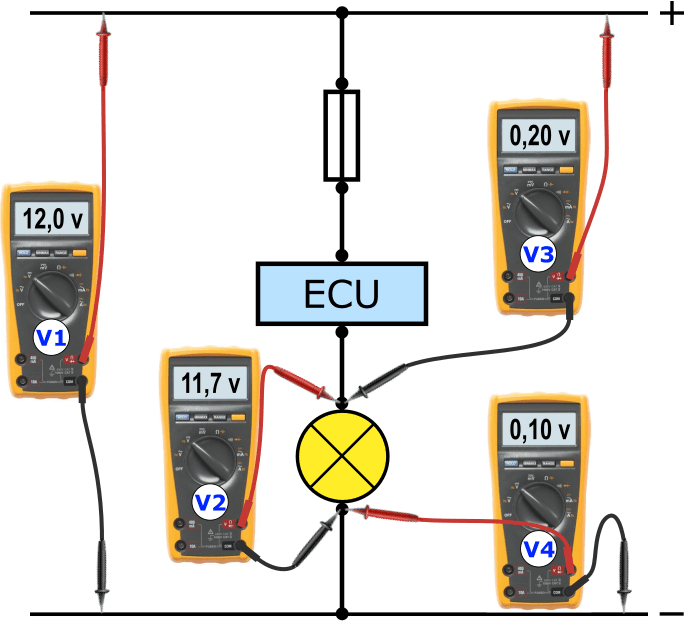
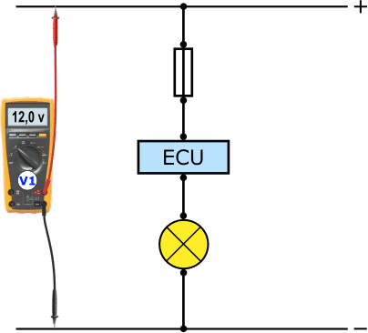
With the V4 measurement we use one voltmeter and take a differential measurement at four specific points. We call these four measurements V1, V2, V3 and V4.
Note: with a PWM / duty-cycle controlled consumer it is not possible to perform this V4 measurement; in that case an oscilloscope must be used!
V1:
The V1 measurement is the first measurement we perform. Here we measure the battery voltage. All voltages that we measure afterwards are compared with this measured value. Before taking measurements, the consumer must be switched on. With heavy consumers, the battery voltage can drop by a few tenths of a volt, without there being a fault. We set the multimeter correctly (see the paragraph on measuring voltage) and place the probes on the positive and negative terminals of the battery.
Is it necessary to start the engine during the V4 measurement? In that case, the V1 measurement will be higher due to the alternator charging voltage. Then perform the measurement again.
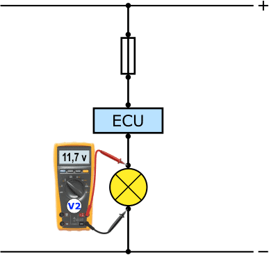
V2:
Next we measure the voltage drop across the consumer. Of course, the consumer must be switched on. With a bulb this is not very complicated: we switch the bulb on with a switch. Sometimes switching the consumer on is a little more difficult, for example with the electric fuel pump in the tank. In that case, start an actuator test with a diagnostic device, or let the engine idle.
- The voltage across the consumer should be about as high as the battery voltage, with a maximum difference of half a volt. If this is the case, there is no voltage loss in the positive or ground side and the V4 measurement is complete;
- If the voltage at the V2 measurement is more than half a volt lower than the V1 value, there is a voltage loss. In that case, we measure the voltages at V3 and V4.
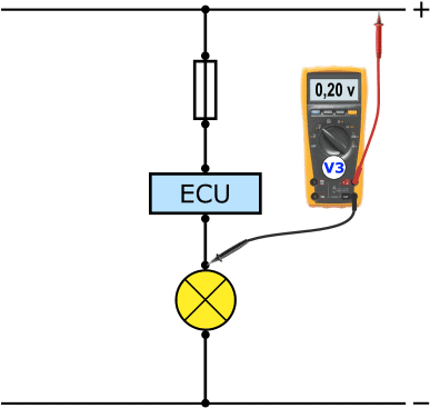
V3:
With this measurement we determine the voltage loss in the positive side, between the positive terminal of the battery and the positive connection of the bulb.
- The loss may be a maximum of 0.4 volts;
- Lower than 0.4 volts is fine;
- At more than 0.4 volts loss, there is a contact resistance in the positive side.
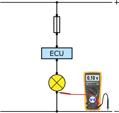
V4:
Finally, we perform the loss measurement between the ground of the bulb and the ground of the battery. The same applies here as for the V3 measurement: a maximum loss of 0.4 volts, otherwise there is a contact resistance.
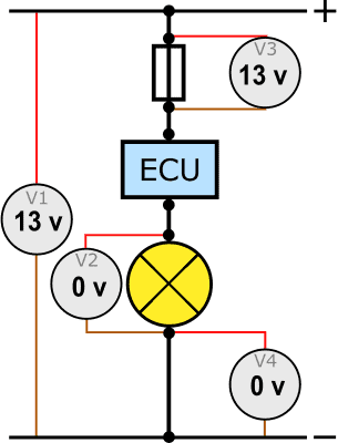
Checking:
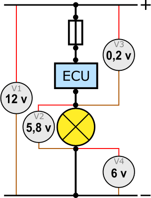
The battery voltage is distributed across the voltage circuit. All partial voltages (V2, V3 and V4) add up to the battery voltage (V1). In the example above, this can be seen in the measured values:
- V1 = 12.0 V
- V2 = 11.7 V
- V3 = 0.2 V
- V4 = 0.1 V
We can then use the following formula:
When the calculation deviates strongly, a measurement error has been made. One should determine which value is illogical. For example, it is impossible for the bulb to burn at 12 volts while the battery voltage is 13 volts and there is a voltage loss of 12 volts.
Below are five possible faults that can be detected with a V4 measurement. To save space and make it as clear as possible, the images of the “real” voltmeters have been replaced by a circle with the number in it.
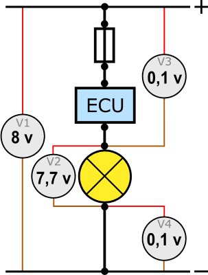
Fault 1 – bulb burns dimly:
The bulb burns more dimly than other bulbs in the vehicle. Logically, because it is operating at only 7 volts instead of 13 volts. The result of V3 shows that there is a 6 volt loss in the positive side. In the part between the positive terminal of the battery and the positive terminal of the bulb there is a contact resistance where 6 volts are consumed. This voltage loss is at the expense of the voltage at which the consumer operates.
Possible causes:
- a damaged wire before the fuse, between the fuse and the ECU or between the ECU and the bulb;
- a poor connection of the fuse in the fuse holder;
- a poor wire connection and/or connectors at one of the black dots in the diagram;
- a fault in the ECU.
To determine where the contact resistance is located, move the negative lead of the V3 meter to the lower side of the ECU. If we still measure 6 volts here, the voltage has not been lost in this wire and the cause is higher up. However, if we measure 0 volts above the wire, this wire is damaged and must be replaced.
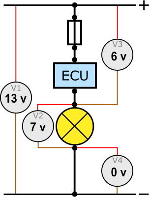
Fault 2 – bulb burns dimly:
Again we are dealing with a bulb that burns more dimly than the rest. In the measured values we see that in measurement V4 there is a voltage loss of 6 volts. Here too, 6 volts are needed to overcome the contact resistance in the ground side.
Possible causes:
- a damaged wire between the bulb and a ground point;
- corrosion between the contact points of the cable eye and the ground point.
If the contact resistance is in the wire, it is sufficient to install a new wire between the bulb and a ground point. If the wire is in order, it may help to unscrew the ground connection and sand and clean it thoroughly, then reinstall the wire and measure again.
Fault 3 – bulb burns dimly:
All bulbs burn dimly. When performing the measurement, we see that the battery voltage is too low (V1). The loss measurements (V3 and V4) are fine. Charging (and possibly testing) the battery is sufficient to solve the problem.
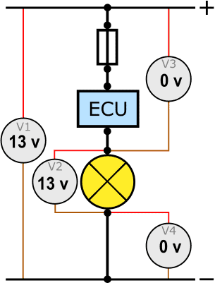
Fault 4 – lamp does not light up:
The lamp does not light up. However, the voltage across the lamp is 13 volts and there is no loss.
Possible causes:
- the lamp is defective: due to a broken filament, the current circuit is interrupted. The 13 volts and ground still reach the lamp, so at V2 we still measure a “good” voltage difference;
- poor connector contact because the metal terminals have lost their clamping force. When repeatedly unplugging and pressing the connector onto the lamp, a gap can form between the metal terminal and the lamp connection.
A defective lamp can often be assessed visually. The filament is visibly broken. If necessary, we measure the resistance of the lamp with an ohmmeter. An infinitely high resistance indicates an interruption.
Fault 5 – lamp does not light up:
Again, we are dealing with a lamp that does not light up. The voltage difference we expect to measure at V2 is now measured at V3. This means that at the top of the fuse there is a good positive supply and at the bottom a good ground. Based on the measured value, the fuse now appears to be a consumer that uses the 13 volts, but this is incorrect.
The cause of this fault is a defective fuse. Just like in the previous fault, where the broken filament caused an interruption in the current circuit, here the fuse is what interrupts the current circuit.