Introduction:
A vehicle contains a large number of temperature sensors:
- coolant temperature;
- oil temperature;
- interior / ambient air and intake air temperature (possibly integrated in the mass air flow sensor);
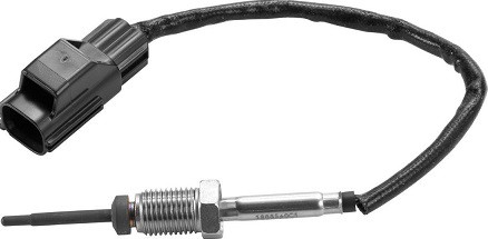
- exhaust gas temperature;
- battery temperature in vehicles with hybrid or fully electric drivetrains.
The temperature sensors above provide the control unit of the respective system with information. For example: the engine control unit uses the signal from the coolant temperature sensor to adjust, among other things, the fuel injection, ignition, idle speed control, EGR operation (if applicable) and the radiator fan control based on temperature. At a low temperature, injection enrichment takes place and the EGR is activated to bring the engine up to operating temperature more quickly. At a higher temperature, the control unit switches on the radiator fan relay. The most commonly used temperature sensors operate according to the NTC principle.

In addition to sensors that send information to the control unit, there are also safety sensors that operate without additional electronics. With such a PTC sensor, the ohmic resistance increases as the temperature rises. An electric motor (such as a wiper or window motor) and a mirror glass are equipped with a PTC sensor. In some cases a PTC sensor is used as a temperature sensor, but in most cases we encounter the NTC.
Classic coolant temperature gauge:
In older cars without control units and NTC temperature sensors, the coolant temperature sender operates with a bimetal element. The image shows the components of the bimetal gauge. A stabilized voltage source of around 10 volts is connected to the gauge. The bimetal strip inside the gauge bends as soon as (more) current flows. This causes the needle to move.
There is a temperature pickup with a bimetal element in the engine block.
The temperature gauge comes into contact with the coolant in the engine.
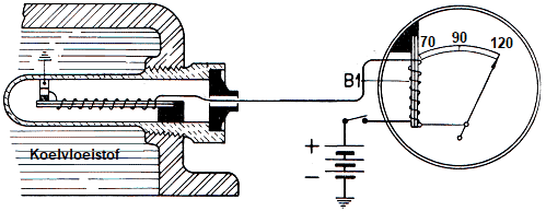
The temperature at which the contacts open depends on the coolant temperature and the current strength. The average current strength then depends on the engine temperature. In some cases, the needle is in the maximum position with the ignition switched off. The bimetal strip is then straight.
NTC temperature sensor:
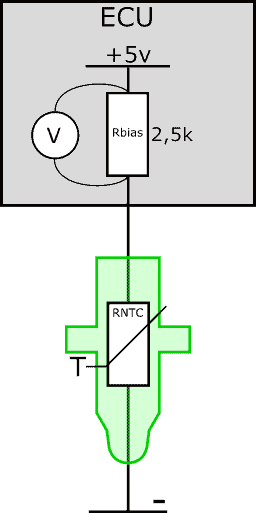
The following image shows a simplified diagram of the ECU and the temperature sensor. The sensor (RNTC) has two wires. The positive wire is connected to the ECU and the negative wire to ground. Inside the ECU there is a bias resistor. The bias and NTC resistors are connected in series. The ECU supplies the series circuit with a voltage of 5 volts.
In a series circuit, the voltage is divided across the resistors. Part of the 5 volts is taken up by the bias resistor. The other part is taken up by the NTC sensor.
The bias resistor has a fixed resistance value; usually around 2500 ohms (2.5 kilo-ohms). The resistance of the NTC depends on the temperature. The voltage that the NTC resistor takes up therefore depends on the temperature.
The ECU measures the voltage drop across the bias resistor. When the temperature changes, the voltage across RNTC changes and with it the voltage across the bias resistor. After all, in a series circuit the voltage is distributed across the resistors; if RNTC takes up 0.3 volts more, the voltage across Rbias drops by 0.3 volts.
The ECU converts the voltage measured across the bias resistor into a temperature. In fact, we are now applying the NTC characteristic, with voltage on the X-axis instead of temperature.
At a high temperature, the smallest change in resistance occurs. The curve in the characteristic drops more steeply between 0 and 20 degrees Celsius than between 40 and 60 degrees Celsius. For that reason, manufacturers often use a second bias resistor for the coolant temperature sensor. The bias resistors are connected in parallel with each other and each has a different resistance value.
As the temperature increases, the ECU switches over to the other bias resistor. This gives us a second NTC characteristic. The second characteristic will have a large change in resistance at a high temperature. This allows us to measure over a larger range and accurately determine the temperature both during warm-up and at operating temperature.
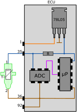
The next image shows the actual circuit in the ECU with the 5-volt voltage stabilizer (78L05), bias resistor (R), the analog-to-digital converter (A/D converter) and the microprocessor. More information about analog signal transmission such as from the temperature sensor can be found on the page: sensor types and signals.
Diagnosis of the temperature sensor:
In case of faults related to the coolant temperature sensor, the following symptoms may occur:
- poor starting of the engine due to, for example, extra injection for a cold engine, while in reality it is already warm;
- overheating: due to a value that is too low, the PWM-controlled radiator fan switches on too late or not at all;
- the engine does not idle smoothly after a cold start;
- as the engine continues to warm up, the idle speed increases;
- exhaust gas emissions are no longer within specification;
- black smoke due to an overly rich mixture;
- hesitation and misfiring with a cold engine;
- the air conditioning cannot be switched on.
Often the above symptoms occur in combination with a check engine light, but that is not always the case. If a fault occurs in which the signal from the coolant temperature sensor remains within tolerance, no fault code is generated.
In reality, the software in the engine ECU constantly checks whether the signal is plausible: in case of major deviations compared to other temperature sensors, or an excessively rapid increase or decrease in temperature, the signal is considered “implausible”. This does result in a fault code.
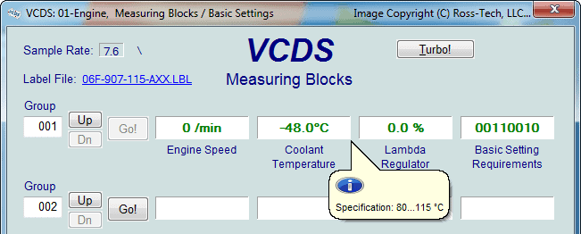
Using diagnostic equipment (often a cheap OBD reader or an interface with phone software is sufficient for this) the coolant temperature can be read out.
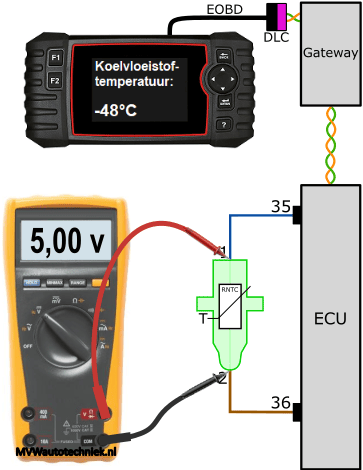
In the image we see a temperature of -48 °C.
The diagnostic program (in this case the measuring value blocks in VCDS) often also provides a reference value that the temperature should meet. Under the current operating conditions, the temperature should be between 80 and 115 °C.
If a sensor value is suspected to be incorrect, we can check the voltages with a multimeter. First we measure the voltages across the sensor at three different temperatures. In the next three images we see a diagnostic computer that is connected via the DLC (Data Link Connector) via CAN bus to the gateway. The gateway also communicates via CAN bus with the engine ECU.


The paragraph “NTC temperature sensor” above describes that the temperature sensor is in series with a bias resistor in the ECU. The 5-volt supply is divided between the bias resistor and the NTC resistor in the sensor housing. When we measure a voltage of 2.3 volts across the sensor, the voltage across the bias resistor is 2.7 volts (2.3 + 2.7 = 5 volts). The 2.7 volts is converted into a temperature by the A/D converter in the interface electronics of the ECU. With a warm engine, the voltage across the bias resistor increases; this can be seen in the last measurement. In that situation this voltage is 4.58 volts.
The images below show the live data and readings with an interrupted ground wire between the sensor and the ECU. On the diagnostic computer a temperature of -48 degrees Celsius can be seen: the ECU measures a voltage of 5 volts across the bias resistor. The ECU generates one or more fault codes with descriptions relating to the sensor:
- signal implausible;
- signal below lower limit value;
- short circuit to positive.


Because no current flows anymore as a result of the interruption, the NTC no longer drops any voltage. The voltage difference between pin 1 of the sensor and pin 36 of the ECU is 5 volts: this is the supply voltage of the sensor. Via pin 35, 5 volts is supplied. Because the sensor does not drop any voltage, we measure a difference of 5 volts between pin 2 (ground connection) of the sensor and pin 36.
In the case where we measure a voltage of 5.0 volts across the temperature sensor (see the next image), we are therefore measuring the total supplied voltage across the component. We are now dealing with an interruption inside the temperature sensor. The voltage loss across the positive and ground wires is 0 volts.
When we disconnect the plug of the temperature sensor and measure in the plug with the multimeter, the same value appears on the multimeter display.
With the result of this measurement, it is clear that we need to replace the temperature sensor.