Topics:
- Introduction
- Fan with viscous coupling
- Electric fan control by means of a thermal switch
- Electric fan control by means of a control unit
- Electric fan control by means of a control unit (relay control)
- Electric fan control by means of a control unit (PWM control)
- Possible malfunctions causing the cooling fan to keep running
Introduction:
In a car we find many types of cooling fans: in the engine compartment, in a multifunctional radio, in battery packs of hybrid and electric vehicles, see: alternative drive. On this page, the engine cooling fan is central.
The cooling fan of a car with an internal combustion engine protects the cooling system from overheating. The cooling fan is available in various designs (see the different paragraphs on this page) but they all have one common characteristic: the plastic fan blades are located at the front end, near the radiator (sometimes at the front, usually at the rear). The fan starts running when the coolant has warmed up, or when the air conditioning is switched on.
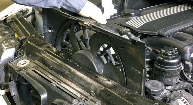
In the image above we see an electric cooling fan of a BMW in a plastic shroud. The cooling fan is removed from the engine compartment by a mechanic by sliding it upwards out of its guides.
The following paragraphs cover the different control methods for the cooling fan.
Fan with viscous coupling:
In addition to the electronically controlled fan, there is also a self‑regulating fan, namely the version with a viscous coupling. No electronics are involved here. A bimetallic strip and liquid silicone fluid ensure that, when temperatures change, the fan is switched on and off by connecting two chambers (the reservoir chamber and the working chamber) to each other.
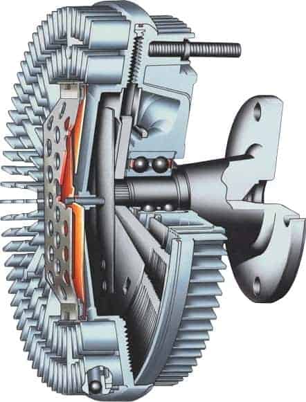
The viscous coupling is attached to the coolant pump with the flange. In the image we see part of the flange. This viscous coupling is bolted to the coolant pump with four bolts. There are also versions with a single central mounting nut.
The viscous coupling is located behind the radiator. The air flowing through the radiator heats the viscous coupling. A bimetallic strip also heats up and therefore bends. As it bends, the bimetallic strip opens a leaf‑spring valve and the silicone fluid can flow from the reservoir chamber to the working chamber. The fluid makes it possible for the rotating movement of the drive plate (engine side) to be transmitted to the fan housing (fan side). The silicone fluid can flow back to the reservoir chamber through the return channel.
- With a cold engine, the fan is switched off. The flange on the coolant pump rotates, but the fan housing is stationary. In this situation, no chambers in the viscous coupling are connected;
- With a warm engine, the fan switches on. The silicone fluid in the working chamber ensures that the fan housing is taken along and starts to rotate.
The degree to which the bimetallic strip has bent (which in turn depends on the air temperature) determines how much fluid can flow into the working chamber. More fluid in the working chamber results in less slip, and thus a higher fan speed. There is always a minimum amount of slip present in the viscous coupling.
While driving, the airstream cools the viscous coupling. That is why the cooling fan will mainly run when stationary or driving slowly.
We can recognize from the sound whether a car has a cooling fan driven by an electric motor or by a viscous coupling. The viscous coupling is driven by the crankshaft via the multi‑rib belt. A higher crankshaft speed results in a higher fan speed. If the fan blows harder as the engine speed increases, and switches off after a few seconds due to cooling, the car is equipped with a viscous coupling. An electric fan will not run faster or slower at idle than when accelerating.
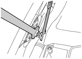
The following image shows the removal procedure for a viscous coupling with a central bolt connection. With two large open‑ended spanners, the bolt connection – and thus the viscous coupling including the fan – can be loosened. By moving the spanners away from each other in opposite directions, the coupling can be removed from the coolant pump. The possibility of removal depends on the type of car. It is not always possible to unscrew the fan with two spanners:
- there is only one nut on the viscous coupling and there is no possibility to lock it. By placing a spanner on the nut and striking it with a hammer, the nut will initially come loose from the coolant pump. Note: this can damage the bearings and seal of the coolant pump!
- the fan can be locked with special tools with several cut‑outs.
Electric fan control by means of a thermal switch:
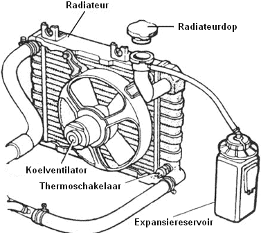
In this system, the electric cooling fan is switched on and off by a temperature‑dependent switch, i.e. the thermal switch. This component is located in the radiator.
The thermal switch is located above the hose that serves as the return hose; the coolant cooled in the radiator returns to the engine via this hose. While driving, the airstream mainly provides sufficient cooling. When the coolant at the outlet side of the radiator becomes too hot, the contacts in the thermal switch close. This creates an electrical connection in the control‑current side of the relay circuit and switches the cooling fan relay on. The fan is actuated and starts rotating.
While the fan is running, the coolant in the radiator cools down again. When the temperature is low enough, the thermal switch breaks the electrical connection. The relay, and therefore the cooling fan, are switched off.
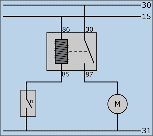
The following wiring diagram shows the control method of the cooling fan. In the diagram we see:
- that it is a waterfall diagram, with terminal 30 (battery positive) at the top, below that terminal 15 (ignition switch output) and at the bottom terminal 31 (battery ground);
- the relay with on the left the terminals 86 and 85 (control‑current input and output) and on the right 30 and 87 (main‑current input and output);
- the thermal switch between terminal 85 and the battery ground;
- the cooling fan between 87 and the battery ground.
The thermal switch controls the control‑current side of the fan relay. When the temperature in the radiator threatens to become too high, the switch closes. The circuit in the control‑current side of the relay is closed; current flows through the coil between terminal 86 and 85. The coil becomes magnetic and pulls the little switch between terminal 30 and 87 closed. As a result, a main current flows from the positive pole of the battery through the electric motor to ground. The fan runs until the contact with the relay is broken.
Electric fan control by means of a control unit:
Nowadays we increasingly see cooling fans that are controlled by a control unit. With this design, a thermal switch is no longer needed: the control unit reads the values from one or more coolant temperature sensors and determines on that basis how to control the cooling fan. The advantages of ECU control are:
- Control (switch‑on and switch‑off moments) can be regulated much more precisely than with the version using a thermal switch;
- One cooling fan can take over the function of what used to be two separate fans (often one large and one small).
The control unit determines when the fan switches on or off and at what speed it runs. The current to the fan does not pass through the control unit: the current is so high that too much heat would be generated in the control unit. ECU‑controlled fan systems can be designed in two ways:
- Relay control;
- PWM control.
These two systems are described in the following paragraphs.
Electronic fan control by means of a control unit (relay control):
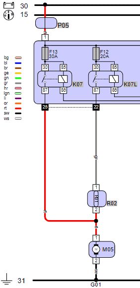
As described in the previous paragraph, ECU control replaces the control system using the thermal switch. The following diagram shows the circuit of a cooling‑fan control system of a Fiat Grande Punto 199. In this diagram we see the following main components:
- R02: series (pre‑) resistor for the fan;
- M05: radiator fan;
- K07: high‑speed relay;
- K07L: low‑speed relay;
The engine control unit determines, on the basis of the coolant temperature and the value of the high‑pressure sensor in the air‑conditioning system, whether and at what speed the cooling fan should run. With the air conditioning switched on, speed 1 is activated by default, and with a (too) hot engine, speed 2 is activated. The fan (M05) can be controlled at two speeds:
- for low speed, the engine ECU switches the coil of relay K07L to ground. The relay switches the main current on, which then reaches the electric motor of the fan via the series‑connected pre‑resistor R02.
- for high speed, the ECU switches relay K07L off and K07 on: the electric motor is now supplied with voltage and current without a pre‑resistor. The fan runs at maximum speed. This occurs, among other things, when the engine is very hot while standing in a traffic jam, or during a fault in the temperature circuit: for safety reasons, the ECU drives the cooling fan at the highest possible speed.
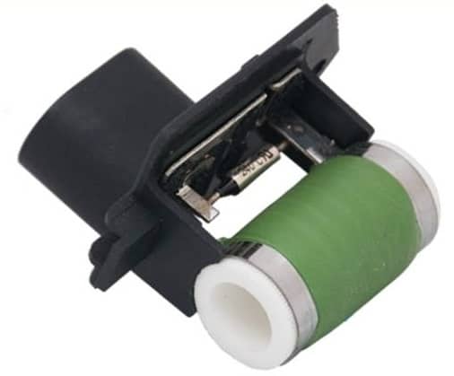
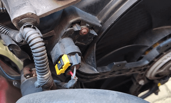
The two images below show the pre‑resistor R02 (left) and the location of the pre‑resistor in the shroud of the cooling fan (right). The white and green plastic part on the pre‑resistor is hollow inside: the cooling fan blows air through it. The metal strips transfer the heat of the resistor to the passing air. This element prevents overheating of the pre‑resistor.
The advantage of the relay circuit and pre‑resistor is that it is a relatively simple system. In the event of a fault, the voltages to and from the relay can easily be measured. For the troubleshooting method, see the page about the relay.
The disadvantage is the use of the pre‑resistor in position 1. A resistor absorbs energy, which ultimately leads to energy loss. In addition, the resistor is susceptible to failure. If the resistor burns out, the fan will no longer work in position 1. When it is suspected that the pre‑resistor is defective, the resistor can be measured. Remove the connector and measure the resistance on the pins of the component. If the result is “OL” or “1.” this indicates an infinitely high resistance and shows that it is defective. A resistance of a few ohms is fine.
When a car is equipped with a single fan relay and the fan starts running at high speed when switched on, this comes at the expense of comfort. The noise of the switching fan can be perceived as disturbing. In addition, when switching on, there will be a peak in power demand: consumers such as the lighting will dim briefly after switching on the relay and starting the fan.
Electronic fan control by means of a control unit (PWM control):
With the PWM‑controlled cooling fan, the fan speed can be increased or decreased steplessly. Whereas with a thermal switch the fan runs at maximum speed after being switched on, or with a pre‑resistor can only run at low or high speed, a PWM control can run the cooling fan at any desired speed. Advantages compared to the system with fixed speeds are:
- More comfort: with the lowest possible speed, the fan is much quieter than when it runs at a (too) high speed using simple on/off control. The constant or low speed will also not affect the lighting, which in the previously discussed system briefly dims;
- Energy‑saving: if little cooling is needed, the fan only has to cool a little. A slowly rotating fan consumes less energy (and therefore also less fuel);
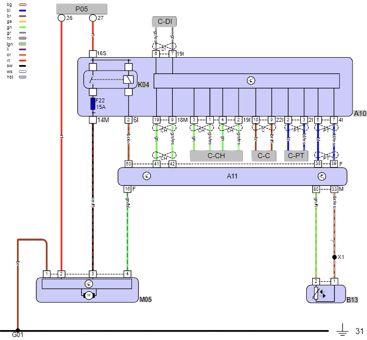
The following diagram is of the cooling system of a Mercedes C‑180. In this diagram we see, among other things, the following components:
- P05: main fuse box;
- K04: main relay;
- A10: engine‑compartment electronics module;
- A11: engine ECU;
- M05: radiator fan;
- B13: coolant temperature sensor.
In this diagram we see that the cooling fan receives a permanent positive supply on pin 2 via the fuse box, a switched positive on pin 3 when relay K04 is activated by the ECU, and a control signal on pin 4 from the engine ECU.
The engine ECU controls the cooling fan with a PWM signal. The control depends, among other things, on the engine temperature.
In the event of faults with the cooling fan, we can check whether the motor receives a permanent and a switched positive (pins 2 and 3) relative to ground (pin 1). If these voltages are correct (at least 12 volts with the engine running), we measure whether the control signal (PWM) from pin 16 on the ECU arrives at pin 4 of the fan.
In the housing of the cooling fan M05 we also see an ECU: this is the control unit of the cooling fan. The engine ECU constantly sends a control signal to the cooling‑fan ECU; even when it is not supposed to run. In this way the cooling‑fan ECU recognizes that the communication is good and that the fan must remain off. When this signal is missing or incorrect, the ECU can no longer recognize whether the fan should remain switched off, or at what speed it should run. For safety reasons, the ECU then drives the cooling‑fan motor at full speed. The driver of the car will notice that, when he/she switches on the ignition, the fan will blow very hard.
It may occur that the fan continues to run at high speed with the ignition switched on or off (strongly depending on the car type). When the control signal from the engine ECU is correct, the cooling‑fan ECU itself may be defective.
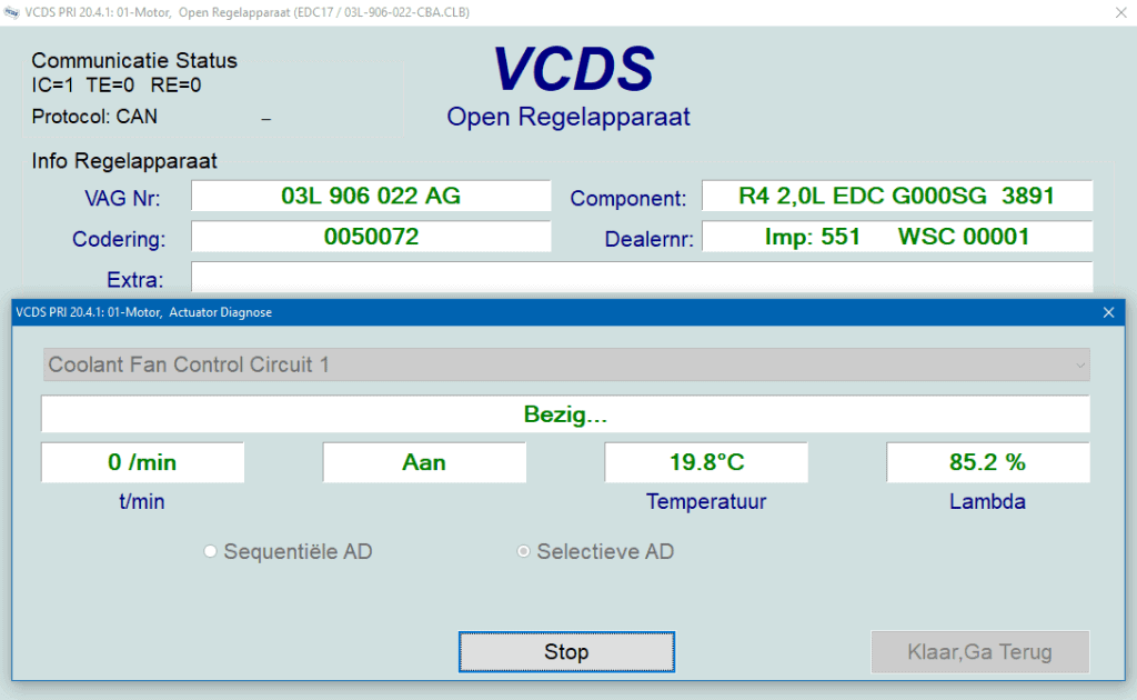
Another possible fault is that the fan is suspected not to run at all. To make the fan run during diagnosis, we can actuate it via the actuator test in the diagnostic equipment and at the same time measure the supply and control voltages.
The following screen shows the actuator test of the cooling fan (Coolant Fan Control Circuit 1) in the VCDS program.
After clicking on “Start” the VCDS program sends the command to the engine ECU that the cooling fan must be actuated. The control then takes place: every five seconds the fan runs at maximum speed and then switches off again.
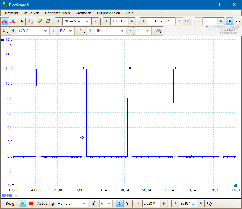
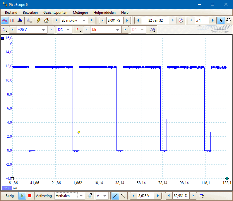
The oscilloscope images below show the PWM control signals with the fan switched off (left) and at full speed (right).
The fan can run at any desired speed by making the active part of the signal longer or shorter.
Possible malfunctions that cause the cooling fan to keep running:
It may happen that a cooling fan continues to run at high speed even when the engine is switched off. Below is a list of the most common malfunctions that cause the cooling fan to switch to a so‑called “limp‑home procedure”.
- One or more fault codes: read out the fault codes from the engine management system or the air conditioning. There may be a fault code relating to the coolant temperature sensor, the high-pressure sensor, or their wiring;
- The coolant temperature sensor is giving an illogical value. Use live data during diagnostics to check the actual temperature;
- The radiator is clogged. This may be either a coolant channel, preventing proper coolant circulation, or a blockage of the airflow. The latter is simple to check: inspect the radiator for visible damage.
- The relay is sticking: this basically only applies to the version with a series resistor;
- There is no proper communication between the engine ECU and the cooling fan ECU: this applies to the PWM-controlled fan ECU. The signals on both ECUs can be measured with an oscilloscope. There should be no difference between them. Do you measure a voltage difference? Then you may be dealing with a broken wire, a contact resistance, or a short circuit.