General:
In a petrol engine, the fuel/air mixture must be ignited at the end of the compression stroke. This happens because the spark plug produces a spark. To make the spark plug spark, a voltage between 20,000 and 30,000 volts is required. An ignition coil converts the battery voltage (around 12 to 14.8 volts) into this high voltage.
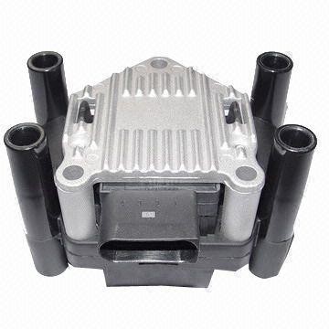
In older systems there is often 1 coil bolted somewhere on the engine block, which is connected to the spark plugs by means of ignition leads. Newer engines often have pencil coils. Each spark plug then has its own coil. The number of coils on the engine can easily be recognised by the presence of ignition leads. If there are ignition leads going to each cylinder, the car has 1 fixed coil or a DIS coil. If there are no ignition leads, then each spark plug has a separate coil on top. Often an engine cover has to be removed to see this.
Coil ignition:
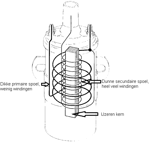
An ignition system makes use of a coil. Regardless of the type (conventional or computer-controlled) the principle comes down to the same thing. Inside the coil are two windings of copper wire around an iron rod (core). The primary winding (on the ignition switch side) has few turns of thick wire. The secondary winding has very many turns of thin wire. A voltage of 12 volts is applied to the primary winding. A current of 3 to 8 amps is passed through this primary winding. This generates a magnetic field. When this magnetic field collapses, a voltage of 250 to 400 volts is induced in the primary winding. Due to the difference in the number of turns, a voltage of up to as much as 40,000 volts is generated in the secondary winding.
The primary winding of the coil has an ohmic and an inductive resistance. The ohmic resistance can be measured with the multimeter, or be calculated from the current or voltage measurements. The inductive resistance relates to the magnetic field that is developed in the primary winding and depends on the rate at which the current changes and the magnetic characteristics of the winding (the L-value). Every coil has a fixed L-value, which depends on the number of turns and the dimensions of the winding and the properties and dimensions of the core.
Conventional distributor ignition with contact points:
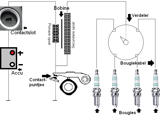
The conventional ignition system consists of a single coil that is switched on and off with contact points, a coil lead, ignition leads and a mechanical distributor with ignition timing advance.
At rest the contact points are closed. A current flows through the primary winding, via the contact points to ground. At that moment a magnetic field is present in the primary winding. When the cam lifts the lever, the contact between the points is broken and an induction voltage is generated. This induction voltage is amplified in the secondary winding and passed via the coil lead to the distributor. The rotor arm in the distributor points to one of the ignition lead terminals. The voltage is passed on to the spark plug, which then produces a spark.
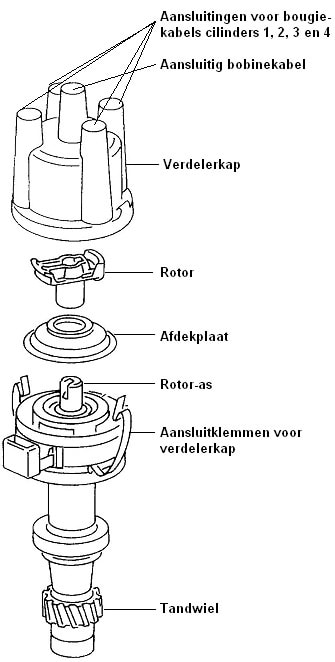
The coil sends a high voltage via the connection of the coil lead to the rotor in the distributor. The rotor in the distributor rotates at half crankshaft speed. That is made possible because, depending on the design, there is a direct connection between the crankshaft and the distributor (as can be seen in the image), or because the rotor is driven directly by the camshaft. After all, the camshaft already turns at half the speed of the crankshaft. The image shows an exploded view of the distributor.
The rotor is maintenance-sensitive. Over time, the contact surfaces between the rotor and the distributor cap will corrode, causing the quality of the spark at the spark plug to deteriorate. By occasionally sanding away the corrosion, or by replacing the worn parts, the quality of the spark remains optimal. By rotating the distributor cap on the rotor, the ignition timing is adjusted.
Computer-controlled ignition:
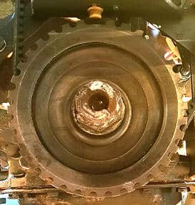
Modern cars are equipped with computer-controlled ignition systems. The engine management system controls the coil. A pulse generator (crankshaft position sensor and possibly a camshaft position sensor) provides a reference pulse that is synchronised with the crankshaft or camshaft. A missing tooth that serves as a reference point is often located in a ring or on the pulley. In the image, the machined crankshaft pulley of the MegaSquirt project can be seen. The pulley has 36 teeth, one of which has been ground away. That is why it is also called a 36-1 reference wheel. Every 10 degrees, 1 tooth passes the sensor (360/36).
Each time the missing tooth passes the sensor, a signal is sent to the ECU.
This reference point is not top dead centre (TDC), as the name often suggests. In reality this reference point is located between 90 and 120 degrees before TDC. This means that when there is no ignition advance, the ignition pulse occurs 9 to 12 teeth after the reference point.
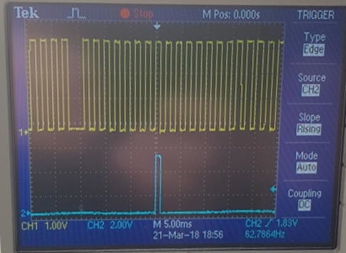
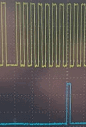
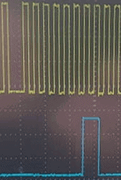
In the image the crankshaft signal (yellow) can be seen in relation to the control pulse of the coil (blue). In the crankshaft signal, the missing tooth where the pulse is absent is visible. In this engine the missing tooth is 90 degrees before TDC (that is 9 teeth of the trigger wheel).
Between the missing tooth (reference point, yellow) and the control pulse (blue) 8 teeth are visible; here we have 10 degrees of ignition advance.
Advancing the ignition has to do with the combustion speed; the combustion needs time to reach its maximum combustion pressure. This maximum combustion pressure is optimal at a crankshaft position of 15 to 20 degrees after TDC. This must be optimal under all operating conditions. The following paragraphs explain what influence the ignition timing has on the combustion pressure, how the ignition advance works and how you can read the dwell time in the scope pattern.
Combustion pressure and ignition timing:
The ignition system must ensure that the mixture in the combustion chamber ignites at the correct moment. At the moment the piston has passed TDC, the combustion pressure must be at its highest. Because there is a time delay between igniting and burning of the mixture (that is when the maximum combustion pressure is reached), the mixture must be ignited well before TDC. In short: the spark plug must have fired before the piston reaches TDC.
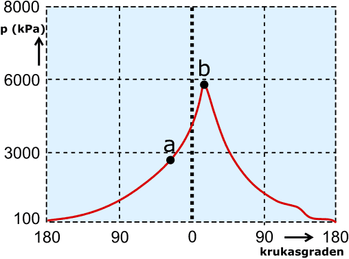
In the following diagram we see the pressure curve (red line) in relation to the crankshaft degrees. At point a the spark plug fires. The piston moves further towards TDC (0) and the combustion pressure rises. Approximately 10 to 15 degrees after TDC (at point b) the maximum combustion pressure is reached.
- if point b is shifted too far to the left, the mixture is ignited too early and the piston is held back as it moves up;
- if point b is shifted to the right, combustion takes place too late. The piston has already travelled too far towards BDC. The power stroke is no longer effective enough.
Ignition advance:
To ensure that the pressure peak occurs at the correct crankshaft position, it is important to advance the ignition when the engine speed is increased. Point b (the maximum combustion pressure) must not be moved. When advancing or retarding the ignition timing, point a (ignition moment) is shifted to the left or right. The combustion time depends on the volumetric efficiency of the engine and the actual air-fuel ratio. The ignition advance is therefore different for every engine. This is also the reason why the crankshaft reference point is set a number of degrees before TDC: between the reference point and TDC there is time to calculate the ignition advance.
With a DIS coil (described later on this page), the crankshaft position sensor is sufficient to determine the ignition timing. The first pulse after the missing tooth is used, for example, to charge the secondary winding of cylinders 1 and 4. Then the number of teeth is counted (18 in this case) to generate the pulse for the secondary winding of cylinders 2 and 3. When the engine is equipped with COP coils, a single reference point is not sufficient. In that case a camshaft position sensor is required to detect multiple reference points.
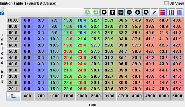
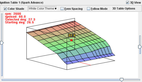
The two images below (ignition advance table and 3D view) show the settings of the ignition map in the MegaSquirt project. These are called the lookup tables, reference or base fields.
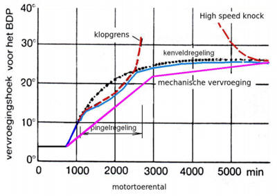
The ignition advance is determined on the basis of the engine configuration. The graphs show the full-load ignition advance curves for (conventional) mechanical distributor ignition (pink line) and a computer-controlled system (blue line). The kink in the pink line is the point where the vacuum advance comes into operation. Furthermore, the lines are dead straight; this is due to mechanical limitations. In a computer-controlled system this can be regulated more precisely; therefore the ignition curve runs as a smooth curve. Between 1200 and 2600 rpm the blue line is pulled down slightly; this has to do with the part-load knock region. It can also be seen that both the conventional and the computer-controlled advance lines end at about 25 degrees. The advance must not increase further, because then there is a risk of “high speed knock”, in other words the knock region at high engine speed.
The ignition map serves as the basis for the ignition advance. From this point the engine management system will try to advance the ignition as much as possible. Too much advance will lead to knocking; this is registered by knock sensors. When the knock sensors detect that the engine is about to start knocking, the engine management system will retard the ignition timing by a few degrees. It will then start to advance again until the knock sensors send a signal.
Dwell time:
When the primary current is switched on, a magnetic field is built up. The current through the winding will not reach its maximum value immediately; this takes time. In the winding there is a resistance that results from an opposing induced voltage. The current will also not rise above 6 to 8 amps. Sufficient energy is built up in 2.3 milliseconds to allow a spark to jump across the spark plug, which is sufficient to ignite the air-fuel mixture. The point t = 2.3 ms is the ignition timing. The current build-up from moment t0 to t = 2.3 ms is called the charging time of the primary winding, or the dwell time.
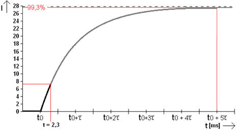
The current build-up in the primary winding stops at approx. 7.5 amps. The current must not rise any further, otherwise the primary winding could become too hot. When the vehicle’s system voltage drops, more time is needed to charge the primary winding. The ignition timing does not change. So charging must start earlier. This can be seen in the image, where the green line represents the switch-on behaviour of the winding at a lower voltage. The charging process starts earlier (delta t) and ends at the same moment as the black line at 7.5 A.
The control of the coil changes; the width of the control pulse affects the charging time of the primary winding. The longer the pulse, the longer the winding has to charge.
In both images, ignition occurs at the eighth tooth (80 degrees before TDC). The right-hand image shows the longer dwell time.
DIS ignition:
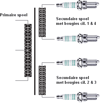
DIS stands for Distributorless Ignition System. As the name implies, it is an electronic distributorless ignition. The signal to ignite comes directly from the ECU, which makes it a computer-controlled ignition. In this ignition system there are 2 coils combined in 1 housing. Each coil provides the spark for 2 cylinders. A single-winding coil is mounted on cylinders 1 and 4, and the other winding is on cylinders 2 and 3.
As an example, we take the DIS coil with the terminals for cylinders 2 and 3. There is no rotor present, which means they will both spark at the same time. Cylinder 2 is at the end of the compression stroke and the coil produces a spark to ignite the mixture. That means the coil also fires on cylinder 3, which is then starting the intake stroke, but because it does not have a combustible mixture at that moment, that does not matter. Later, when cylinder 3 is in the compression stroke, cylinder 2 will be in the intake stroke and will receive the unnecessary spark. The wasted spark in the cylinder where no combustion takes place does not cause the spark plug to wear out more quickly. The spark then only needs a voltage of 1 kV (1000 V) instead of 30 kV when igniting a mixture.
The advantage of the DIS coil is that it practically requires no maintenance. The coil is maintenance-free. The disadvantage of this coil is that moisture sometimes penetrates between the cable and the connection shaft in the coil. Moisture causes corrosion on the contacts, which turn white or green. The spark voltage drops due to the large voltage loss caused by the corrosion. The engine may begin to shake and vibrate slightly, without any actual fault being stored in the ECU memory. In the case of a complaint like this, it is advisable to remove the cables from the coil one by one (with the engine switched off!!) and check whether the contacts are nicely gold-coloured and whether there are no traces of corrosion visible in the cable and in the shaft. The corrosion is very aggressive and will slowly return after cleaning. The best solution is to replace the complete coil together with the relevant cable.
One coil per cylinder:
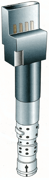
In this ignition system, the (stick) coils, also called COP (coil on plug) coils, are mounted directly on the spark plug. Here too, the engine control unit (ECU) controls the ignition. Both the current and the ignition timing are calculated by the control unit. The operation is the same as an older coil; this coil also has a primary and secondary winding. Via the connector at the top, the primary winding is supplied with voltage and is interrupted internally by a transistor.
The disadvantage of these coils is that they are mounted in the spark plug well and therefore become extremely hot. Although they are designed for this, they do sometimes fail. This can be recognised by a cylinder misfire, causing the engine to shake. When this happens, the lambda sensor will detect that one coil is not igniting the fuel and the fuel injection on the corresponding cylinder is stopped. That cylinder then no longer contributes at all. This prevents unburned fuel from entering the exhaust, which would damage the catalytic converter. A faulty coil can often be recognised by the fact that the engine runs very erratically (and the engine warning light is on, although there can be countless causes for this light to come on).
More information and causes of misfire can be found on the page cilinderoverslag.
If a coil is suspected to be defective, the primary ignition pattern can be viewed with the oscilloscope, provided the engine is in limp-home mode and the ignition and injection have been disabled while the engine is running.
Measuring the primary ignition pattern with the oscilloscope:
The coil generates the voltage so that a strong spark can develop at the lower side of the spark plug. The coil must generate a voltage of approximately 30,000 to 40,000 volts in order to make a spark jump across the spark plug. For this, an ionisation voltage of 300 to 400 volts must be generated in the primary winding. In the course of the voltage through the primary winding we can see whether this process is proceeding correctly. The voltages of the primary and secondary windings are transferred to each other, although the levels in the secondary winding are about 100 times higher. This makes it possible to see in the primary voltage curve whether the coil is in good condition and whether the spark plug is sparking properly. The oscilloscope image below was measured on the primary winding of a coil.
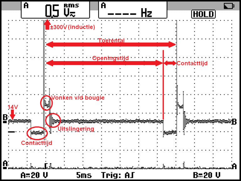
From left to right:
- 14 volts: at rest we measure 14 volts at the positive and ground side of the winding in the coil;
- Dwell time: the primary winding is grounded on one side. A differential voltage of 14 volts arises between + and ground, causing current to flow through the winding;
- 300 volts (induction): the power stage in the ECU or ignition module stops the control and an induction of approximately 300 volts is generated in the primary winding. We call this the ionisation voltage. In the secondary winding a voltage of 30,000 volts is generated. This voltage is needed to make the air between the electrodes of the spark plug conductive and to make a spark jump;
- Sparking of the spark plug: from the spark line we can see that the spark plug is sparking;
- Ring-down: in this phase the residual energy is discharged. This depends on the LCR value of the circuit (L value of the coil and the capacitance of the capacitor).
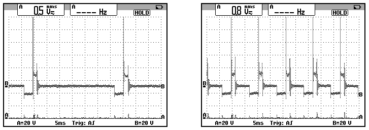
With the opening time in the oscilloscope image, we mean the opening time of the contact points. In a computer-controlled ignition system this is no longer applicable. However, based on the point at which the ionisation voltage of the second spark appears in the image, we can determine the engine speed. In the oscilloscope images below, the primary ignition patterns at a low engine speed (left) and high engine speed (right) can be seen.
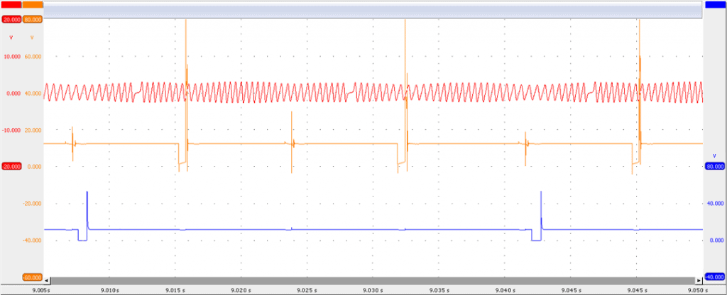
With an oscilloscope we can display the ignition pattern and injection pattern in relation to the crankshaft signal. The reference wheel contains one reference point. After each revolution of the crankshaft, an ignition event takes place. We know that the crankshaft has to rotate twice for one complete power cycle. From this we can recognise that we are dealing with a DIS coil. A “wasted spark” therefore occurs. The injector patterns confirm this: injection takes place every second crankshaft revolution.
If there is a suspicion that a coil is defective, viewing the secondary ignition pattern can be used to determine whether there is a problem in the secondary ignition. The resulting image shows the ignition pattern of cylinder 6 (blue) and of cylinder 4 (red) in which a fault is present. The explanation follows below the image.
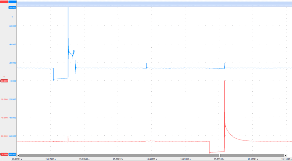
In the primary pattern of cylinder 4, the ionisation voltage can be seen, but then the energy dissipates. The pattern now shows similarities with the characteristic voltage curve of a solenoid injector. What can we identify in this pattern:
- Cylinder 6 (blue) is fine. We use this pattern as a reference;
- Cylinder 4: the ionisation voltage is fine. Energy is being generated in the primary winding. The primary winding is good;
- The control from the engine ECU or the external ignition module is fine;
- The secondary curve is not visible;
- The primary and secondary winding therefore do not exchange energy;
- The secondary winding is open-circuit.
Experience shows that the secondary winding of a coil can fail due to heat. With an oscilloscope we can trace this defect. Note: if the engine has gone into limp-home mode, the control may have been disabled. Therefore perform the measurement immediately after, or during, starting the engine.