Topics:
- Indirect and direct injection
- Fuel pressure control with indirect injection
- Injection strategy multipoint injection
- Electromagnetic injector (MPI)
- Piezo injector (DI)
- Injection strategies direct injection
- Dual injection
- Measuring voltage and current pattern on a multipoint injector
- Injection timing relative to crankshaft position
- Current limitation in the ECU
- Determining the required amount of fuel
- VE table
- AFR table
Indirect and direct injection:
The types of injection systems of a petrol engine are divided into indirect injection before the throttle valve, indirect injection per cylinder and direct high-pressure injection. In the paragraphs on this page these different injection systems are explained.
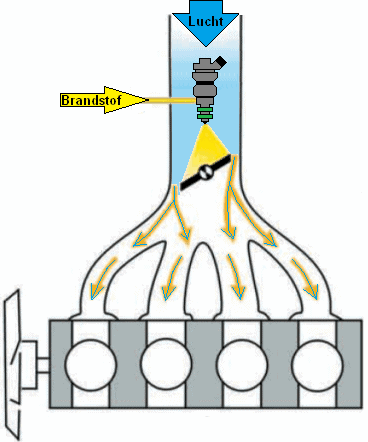
Indirect injection:
There is an injector in front of the throttle valve. The fuel is sprayed against the throttle valve and mixes there with the air flowing past. The major disadvantage is that there is no precise fuel metering per cylinder; one cylinder always receives slightly more or less than the other. The system is therefore not controllable and as a result is no longer used nowadays with regard to emission standards. This system is also called central injection (Monopoint).
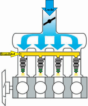
Indirect injection:
Each cylinder has its own injector. The injector sprays the fuel onto the intake valve. The air flowing past also provides mixing in this system before the air-fuel mixture enters the combustion chamber. The advantage compared to indirect injection before the throttle valve is that the amount of fuel can be regulated much more precisely. This system is also called MPI (MultiPoint Injection) or PFI (Port Fuel Injection).
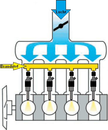
Direct injection:
The injectors in DI (Direct Injection) or DISI (Direct Injection Spark Ignition) are located next to the spark plug, at the top of the combustion chamber. The fuel is injected by this injector at a high pressure of approx. 200 bar during the intake stroke. The major advantages of this system are that the fuel quantity can be metered even more precisely, that it is possible to inject several times during the intake stroke and that the air-fuel mixture is cooler. This has enabled manufacturers to increase the compression ratio of the engine. The injector may be of the piezo type or the solenoid type.
For DI, higher injection pressures are required than with MPI / PFI, because the injection takes place during the compression stroke; the fuel must still be sufficiently atomized while the air in the cylinder is being compressed. Therefore, a separate high-pressure pump is present in DI systems. The high-pressure pump builds up a fuel pressure in the fuel rail. The injectors are connected to this fuel rail with lines. As soon as the engine management sends a signal to the injector, it will open and close at the desired time.
The advantages of DI compared to PFI include:
- More precise injection;
- Multiple injections possible;
- Injection timing can be adjusted;
- Higher effective pressure above the piston possible (making downsizing with a higher compression ratio possible);
- Lower fuel consumption, lower CO2 emissions.
The disadvantages include:
- Higher system costs due to a high-pressure fuel pump, advanced injectors, more complex cylinder head;
- Increased soot emissions (PM emissions);
- Direct injection into the combustion chamber provides cooling instead of the heat needed for fuel evaporation.
An engine with dual injection uses the advantages of both systems. Direct and indirect injection can be switched depending on the operating conditions. The operation and application of dual injection is described in the paragraph of the same name on this page.
Fuel pressure control with indirect injection:
A constant fuel pressure is a prerequisite for being able to control fuel injection accurately. At the top of the injector there is the fuel pressure (rail pressure) and at the bottom the intake manifold pressure. The pressure in the intake manifold varies with changing engine load and, without a pressure regulator, would affect the fuel pressure difference and thus the injection quantity. For that reason we use a fuel pressure regulator. In this paragraph we look in more detail at the operation and purpose of this regulator.
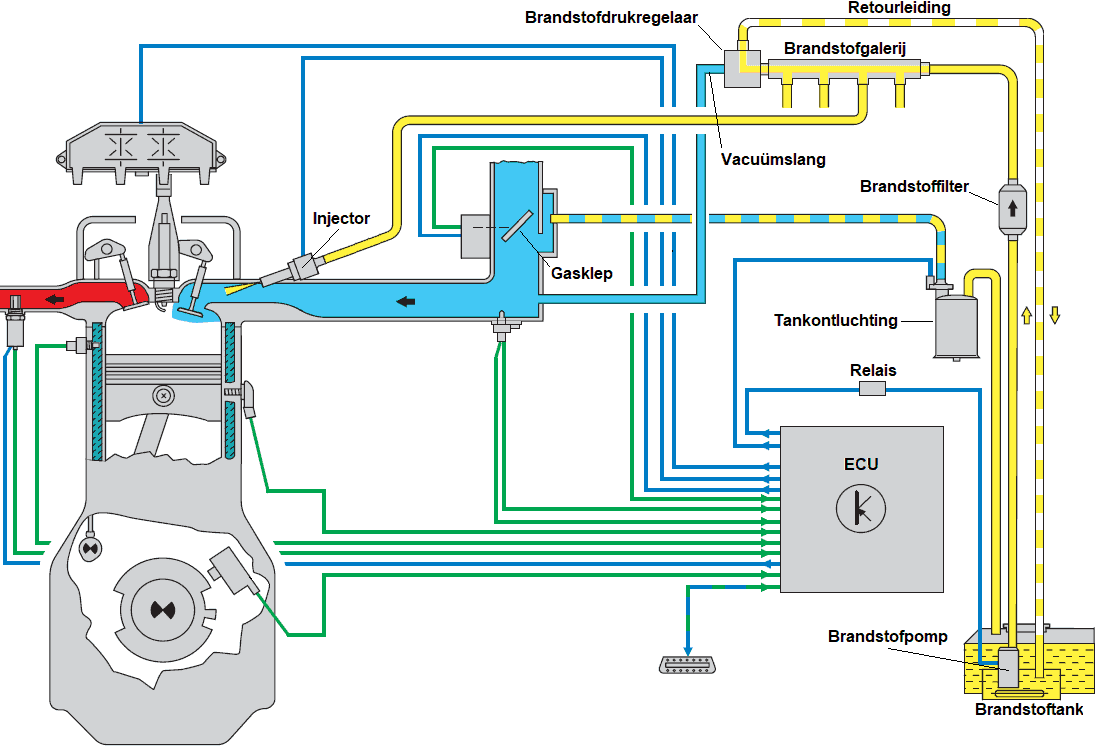
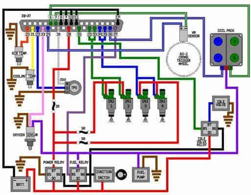
The image below shows the components of an indirectly injected petrol engine with multipoint injection. We follow the fuel flow from the pump in the tank up to the injector.
When the ECU actuates the fuel pump relay, the pump starts running. The pump draws the fuel from a point as low as possible in the fuel tank and pushes the fuel flow towards the fuel filter. Dirt particles in the fuel remain behind in the filter material. The filtered fuel then reaches the fuel rail. In most cases the fuel rail is mounted directly on the injector inlet.
There is a constant pressure in the fuel rail: only when the injector is electrically actuated by the ECU (see the blue wire) does the injector open and fuel is injected into the intake manifold onto the opened intake valve. The amount of injected fuel depends on:
- the injection time (is determined by the ECU by lengthening or shortening the injection signal);
- the fuel pressure (with an injection time of 2 milliseconds the injector will inject more at too high a fuel pressure than the ECU has calculated).
The fuel pressure in the fuel rail (also called rail pressure) is adjusted according to the engine load. We will look at this in more detail in the next paragraph.
Without using a pressure regulator, the following situations arise:
- At idle speed, the higher vacuum (thus a low air pressure) in the intake manifold would result in an undesirably higher petrol pressure;
- During acceleration there is less or almost no vacuum (full load) and the petrol pressure would drop, whereas a higher petrol pressure is desired.
With the fuel pressure regulator the petrol pressure in the fuel rail is increased or decreased according to the air pressure in the intake manifold. We can regard the fuel pressure regulator as a dynamic valve which provides an opening between the supply line from the fuel pump and the return line.
On the right we see a fuel pressure diagram in which, thanks to the pressure regulator, the relative pressure difference under all conditions (idle, part load and full load) is 4 bar.
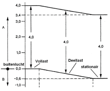
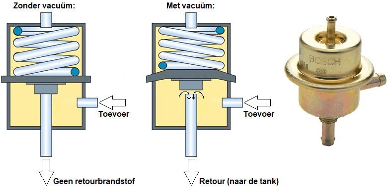
The explanation below relates to the images in which the pressure regulator is shown in the situation without and with vacuum. On the right a fuel pressure regulator from Bosch is shown, which has been used by several car manufacturers.
Without vacuum (left):
The pressure regulator is closed at rest: the spring presses the diaphragm shut, preventing the supplied fuel from entering the return line.
With vacuum (centre):
When the pressure above the diaphragm is lowered, the fuel pressure on the supply side pushes the diaphragm upward against the spring force. An opening is created, allowing the supplied fuel to be discharged through the return line to the fuel tank.
Injection strategy multipoint injection:
With (indirect) multipoint injection three different injection methods are used:
- Simultaneous: all cylinders are injected at the same time.
- Grouped: the injection takes place per group; there is a distinction between one or more small groups.
- Sequential: each injector is controlled separately and thus has its own injection moment.
The engine management system in the image below illustrates grouped injection. The injectors of cylinders 1 and 2 share a common power supply (red) and are both switched to ground at the same time (green). The injectors of cylinders 3 and 4 are the same, but are controlled separately from cylinders 1 and 2.
Electromagnetic injector (MPI):
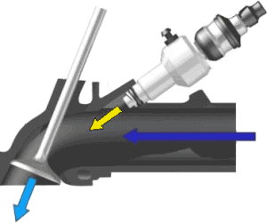
The electromagnetic injector is used on very many petrol engines that do not use (direct) high-pressure injection with a separate high-pressure pump. The fuel at a constant pressure of 1 bar is present at the inlet of the injector. The fuel pressure is provided by the fuel pump in the tank. With multipoint injection (this is described later on the page) each cylinder has its own injector. This injector is mounted in the intake manifold and already sprays fuel in at a pressure of up to 6 bar before the valve opens. The fuel then has enough time, as soon as the intake valve starts to open, to mix with all the oxygen (indicated by the dark blue arrow in the image) that flows into the cylinder.
The engine control unit looks at the position of the crankshaft to control the injection timing and the ignition timing. Based on several factors (engine and ambient temperature, load, speed, etc.) it will send a signal to the injector at the right moment to open. The connector of this injector contains two wires. One wire carries a constant positive voltage of around 14 volts. The other wire is switched to ground by the ECU to allow current to flow through the injector coil. When the coil is sufficiently energized, the injector needle opens against the spring force. When the actuation stops, a spring pushes the injector needle back. The fuel supply is then shut off. At the moment the actuation stops, the coil is still electrically charged. The energy in the coil forms an induction peak, which can be observed on the oscilloscope. The induction voltage briefly amounts to around 60 volts.
These injectors are supplied with fuel by the fuel rail (also called the fuel gallery). The lift pump in the fuel tank provides the pressure in the fuel rail. The fuel pressure in the rail is constant (approx. 4 bar). Because the pressure is so low, the injectors are secured with a retaining clip and an o-ring for sealing. Especially on older cars where the system is dismantled, it is advisable to replace the o-rings before installation.
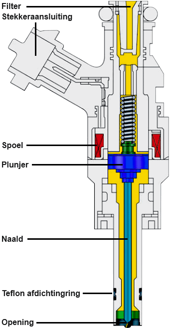
The housing of an injector is usually made of plastic. At the top of the housing we find the connector, which is internally connected to the coil. At the top there is a rubber o-ring over which the fuel rail is slid. At the bottom, o-rings or Teflon sealing rings can be found. An o-ring is mainly used on MPI injectors with low-pressure injection, while Teflon rings are found on engines with high-pressure injection, such as an FSI engine.
The coil is wound around the core of the injector. In the accompanying image the coil is marked in red. In the middle of the injector, also inside the coil, there is a plunger. This plunger has a mechanical connection to the needle. Above the plunger is a spring that holds the plunger and thus the needle in its seat, closing off the injection opening.
At rest, the voltage on both terminals of the coil is approximately 14 volts with respect to ground. To make the injector inject, the engine ECU supplies one side of the coil with ground, while the other side receives positive voltage. At that moment current begins to flow through the coil, resulting in the formation of a magnetic field. This magnetic field pulls the plunger and thus the injection needle upwards.
When the injection must be terminated, the ECU interrupts the ground connection, causing the magnetic field to disappear. The spring pushes the plunger back down, and the needle shuts off the fuel supply to the combustion chamber.
The injector usually has several openings. These openings are very small, so the fuel is injected from the injector into the combustion chamber as a mist. The finer the mist, the more easily it evaporates.
Piezo injector (DI):
Piezo injectors can be used in both petrol and diesel engines. BMW was the first brand to use piezo technology in petrol engines, but has stopped doing so on newer engines.
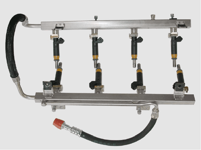
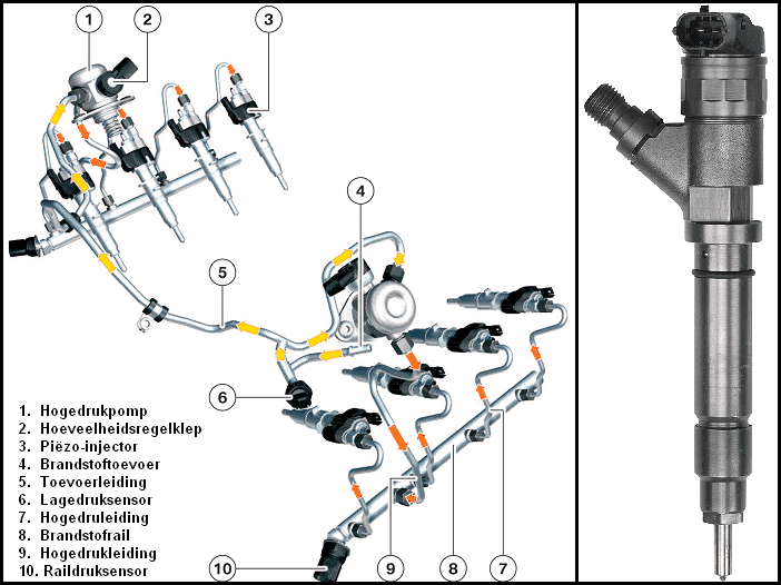
A piezo injector is a component of the high-pressure injection system. A separate high-pressure pump provides the pressure in the fuel rail. This fuel rail distributes the fuel to all injectors (see image). Due to the very high pressures, aluminium lines with unions are used. The unions (which are screwed onto the line and injectors) must always be tightened with the correct torque. This is stated in the repair manual of the respective engine.
The piezo element in the injector has the property of changing in length when a positive or negative voltage is applied to it. This property is used in the injector. As soon as the engine control unit supplies a control voltage of approx. 100 to 150 volts, the piezo element expands by about 0.03 mm. This change in length is enough to create a connection between the high- and low-pressure chamber. Injection starts immediately. The piezo element can switch on and off within one thousandth of a second. Together with the very high injection pressure of up to 2000 bar, this results in extremely fast and precise injections. Several injections in succession are also possible thanks to these speeds.
Multiple injections during the intake stroke have the advantage that the air-fuel mixture is optimal. Due to the high pressure, the fuel droplets are atomized ultra-fine, which allows them to mix even better with the air. Up to 8 injections can take place during the intake stroke. This has positive effects on fuel consumption, power and exhaust emissions.
Injection strategies direct injection:
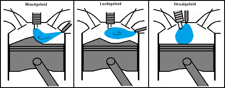
The injection strategy of direct injection has several variants: wall-guided, air-guided and spray-guided (see the images below). In these situations there is a stratified combustion process. This does not apply in all operating conditions.
- Wall-guided: The piston guides the fuel cloud towards the spark plug. The distance between the spark plug and injector is large. Used on GDI and HPI engines.
- Air-guided: The air movement carries the fuel cloud to the spark plug. The distance between the spark plug and injector is large. Used on FSI and JTS engines.
- Spray-guided: The spark plug is located at the edge of the fuel cloud. The distance between the injector and the spark plug is small. Used on BMW engines.
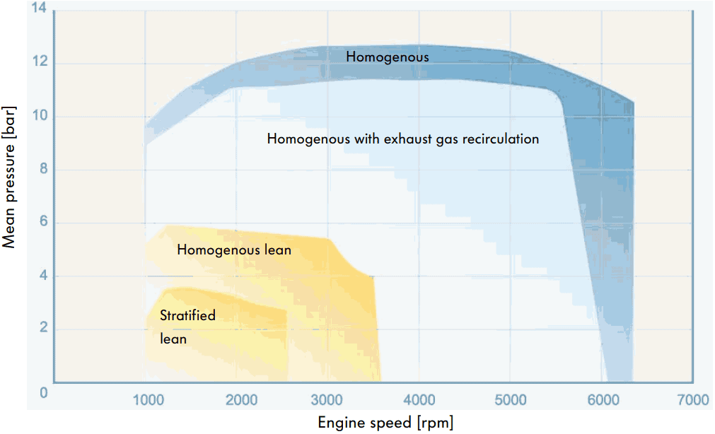
As already indicated, in directly injected petrol engines there is not a stratified combustion process under all operating conditions. Engines with spray-guided direct injection can run stratified at part load. A stratified combustion process means that various layers of air are present in the combustion chamber. Near the spark plug the lambda value is 1. Further away from it, the lambda value becomes increasingly higher (leaner, thus more air). This air provides an insulating air layer. In a stratified process the injection timing is later than in the homogeneous process. With the aid of stratified injection the throttle valve can be fully opened so that it throttles the air less. Because the intake air is unthrottled, it experiences less resistance and can thus be drawn in more easily. Because the lambda value in the combustion chamber with stratified injection is still lower than 1 due to the insulating air layer, this does not cause any problems with combustion. During the stratified process, fuel consumption decreases.
With a homogeneous mixture the lambda value is 1 everywhere. For a petrol engine this means that the air-fuel ratio is 14.7:1 (14.7 kg of air with 1 kg of fuel). Every engine can run homogeneously. If enrichment takes place, the lambda value will fall and if the mixture is made leaner, the lambda value will rise:
<1 = Rich
>1 = Lean
An engine will always continue to fluctuate between rich and lean in order to keep the catalytic converter working properly. The lambda sensor sends the data to the engine management system.
At full load the engine always runs homogeneously. This provides a higher torque than in a stratified process. When the engine runs homogeneously, the fuel is injected early. When pulling away from standstill the engine also runs homogeneously. At that moment, a higher take-off torque is available than when the engine would run stratified.
The characteristic below shows the operating situations at different speeds in relation to the combustion pressure, with and without the use of EGR.
Dual injection:
The VAG group uses petrol engines with dual injection to comply with current emission standards. Engines with dual injection have two fuel injection systems: a low-pressure and a high-pressure system.
- The low-pressure system contains MPI injectors that have been used for decades. The MPI injectors are fitted in the intake manifold and inject onto the intake valve at a pressure of 4 to 5 bar;
- The high-pressure system contains high-pressure injectors which inject directly into the combustion chamber with an injection pressure of up to 150 to 200 bar.
The engine management system determines which injector is actuated.
The following image shows a cross-section of the cylinder head with the two fuel systems.
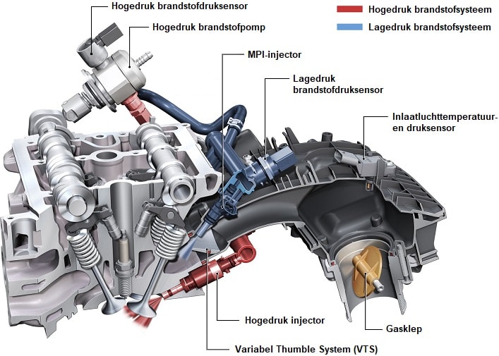
The MPI injection provides better mixing between air and fuel. The direct injectors are used at idle speed and full load. With direct injection, better cooling is obtained, allowing a higher compression ratio. However, the mixing of air and fuel is not optimal. This leads to more soot emissions. Engines with direct injection are therefore nowadays equipped with a particulate filter. With dual injection this is not an issue. The “variable thumble system”, abbreviated VTS, is a version of a variable intake manifold that allows the airflow to experience better flow. The “thumble” is an airflow that is set into a swirl as it flows into the cylinder. The air swirl is needed to mix the fuel from the MPI injector properly with the air.
The dual injection in combination with VTS results in better exhaust gas emissions. An additional advantage is that the intake valve is cleaned by the MPI injector. Engines with direct injection often suffer from a contaminated intake tract (intake manifold and intake valves), which causes problems such as a restricted air supply. In the extreme scenario, the intake becomes so clogged that the intake valve can no longer seat properly on the cylinder head and eventually burns because it cannot dissipate its heat sufficiently.
It is known that VAG engines with dual injection are equipped with only direct injection in the United States. The intake manifold is blanked off. This is because at the time of writing, environmental requirements in Europe are stricter than in the US, and for cost reasons the manufacturer does not equip the engines for markets with less stringent emission standards with such expensive systems.
Measuring voltage and current on a multipoint injector:
The oscilloscope can only measure voltage. Test leads can be connected in parallel across the electrical components. Measuring current in series is not possible. With an inductive current clamp, however, the current can be measured. The Hall sensors in the current clamp measure the magnetic field and convert it into a voltage. This voltage can be measured with the oscilloscope. In this case there is a conversion factor of 10 mV per ampere; every 0.010 volt that the current clamp outputs can be converted to 1 A.
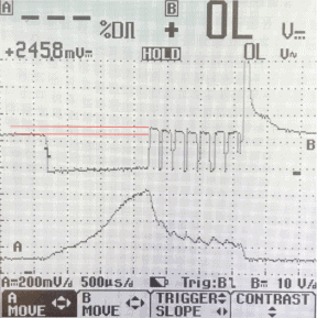
The next scope pattern shows the voltage and current profile of an electromagnetic injector.
- Red: voltage profile;
- Yellow: current profile.
At rest, the voltage is 14 volts. There is no voltage difference at the connector, so no current flows. The ECU switches one wire to ground to actuate the injector. Due to the voltage difference, current starts flowing through the injector coil.
The yellow line shows the current profile: at the moment the voltage drops to 0 volts, the current build-up starts. Charging the coil takes time. The current does not rise further than about 0.9 A. Halfway through the current build-up we see a kink in the line: this is the moment when enough magnetism has built up to lift the needle from its seat. The injector starts injecting.
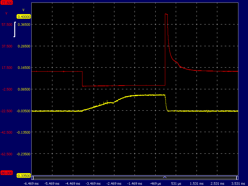
The ECU interrupts the ground connection to stop the control. The residual energy in the coil causes an induction voltage of about 60 volts. The injector stops injecting because the spring presses the needle back onto its seat. This can be seen in the scope pattern as the bump in the voltage signal.
When the engine runs irregularly and misfires occur, this can have a number of causes:
- No or a poor spark due to a defective spark plug, spark plug wire or ignition coil;
- Restriction in the fuel supply due to a clogged fuel filter, defective pressure regulator, problem with the fuel pump or injector;
- Loss of compression as a result of a problem with the piston rings, defective head gasket or valve seals.
During diagnosis, a scope can be used to check whether the injectors are still functioning correctly. At the beginning of this paragraph, measurements were shown in which there was no malfunction. As an example, the blue lines indicate what the voltage and current profile of a defective injector would look like.
If the injector control is correct, but no kinks are visible in the voltage and current pattern, it can be concluded that the injector needle is not moving. Because the injector of one cylinder is not working properly and the other injectors are functioning correctly, the patterns of different injectors can be compared very well.
If you carefully tap the injector, the injector needle may sometimes come loose. In that case, the engine immediately starts running more smoothly and the kinks can then be seen again in the scope patterns. However, this does not guarantee a permanent solution; the chance is high that the problem will return within a short time. The faulty injector must be replaced.
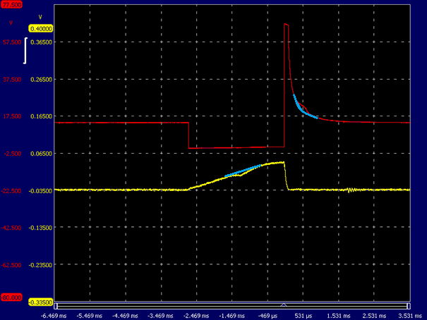
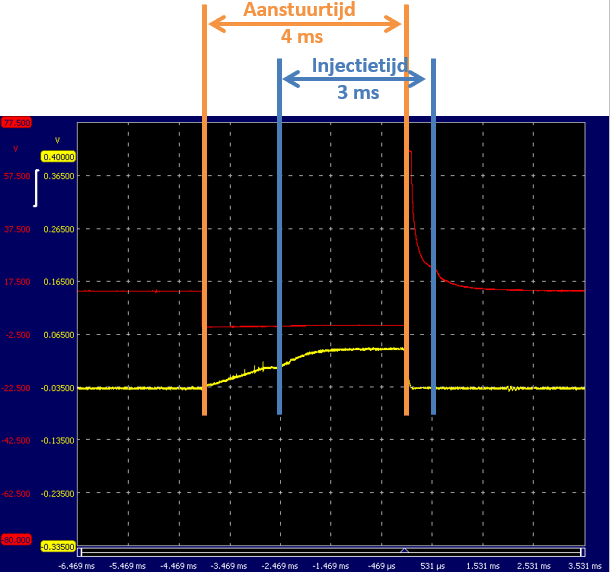
The needle in the injector only opens after the coil is sufficiently charged. As a result, the injector does not inject fuel immediately when the ECU starts the control. After the control ends, the spring presses the injector needle onto its seat. This also takes time. The control time is usually not equal to the injection time. The following image shows the voltage and current profile of the same injector as above, but now at an increased engine speed.
- Start of control: the ECU switches the control wire to ground. Current flows through the coil of the injector to open it. The kink in the current pattern indicates the moment when the injector needle opens. The current then rises slightly and remains constant. The injector needle remains open.
- End of control: as previously described, we recognize the moment when the injector needle has closed by the small bump in the voltage pattern.
The control lasts 4 ms, but the actual injection time is 3 ms. The difference between these is called the “delay”. The ECU therefore controls the injector for 4 ms to have it inject for 3 ms.
Injection timing in relation to crankshaft position:
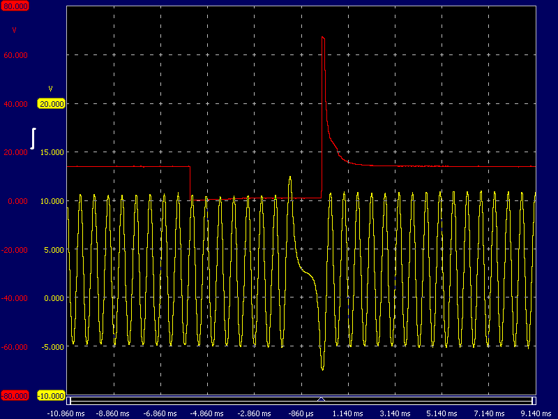
An oscilloscope can be used to observe the injection moment. Channel A (red) is connected to the ground wire of the injector and channel B (yellow) is connected to the wire of the crankshaft position sensor. While the engine is running, we can use this scope pattern to determine the injection timing and injection duration.
The scope pattern was recorded at idle speed. The red voltage pattern shows the opening and closing of the injector (see the paragraph: measuring voltage and current on a multipoint injector). At the time -2.860 ms, the control starts; the voltage of 12 volts drops to 0 volts. This is the point at which the injector coil is switched to ground and current starts to flow. The control of the injector ends when the red line rises again. Due to the energy built up in the coil, an induction voltage of more than 60 volts occurs. The voltage then gradually drops to 12 volts; the injector is now switched off again.
The red AC voltage comes from the inductive crankshaft position sensor. Every time the teeth of the trigger wheel pass the crankshaft sensor, a sinusoidal AC voltage is generated. The trigger wheel contains 60 teeth, 2 of which have been ground off. The two missing teeth form the reference point at which the engine management system recognizes that the pistons of cylinders 1 and 4 are between 90° and 120° before TDC (top dead centre). After the missing tooth has been recognized, the engine management system has time (possibly in combination with the camshaft sensor) to determine the correct injection and ignition timing and to actuate the injector and ignition coil before the piston reaches TDC.
In the scope pattern, the moment at which injection starts can be seen; injection starts at the fourth pulse of the crankshaft sensor. Assuming there are 60 – 2 teeth present, and with a tooth every 6° of crankshaft rotation (360° for 1 revolution / 60 teeth), the injection takes place 24 degrees after the reference point. The missing tooth is located 90° before TDC, so the injection begins (90° – 24°) = 66° before TDC.
At an increased speed of 2000 rpm, the pulses of the inductive crankshaft sensor are closer together. The frequency of this signal is translated into engine speed by the engine management system. Depending on the engine speed, the load (measured by the MAP sensor) and the temperatures of the intake air and coolant, the required injection time is determined. The injection timing occurs earlier and the injector is grounded for longer: the injector starts injecting earlier and injects for longer.
From the start of the control to the trigger point (arrow at the point where the injector switches off), the control lasts approximately 5.2 ms. The time the injector is actuated is not equal to the actual injection time (see the previous paragraph).
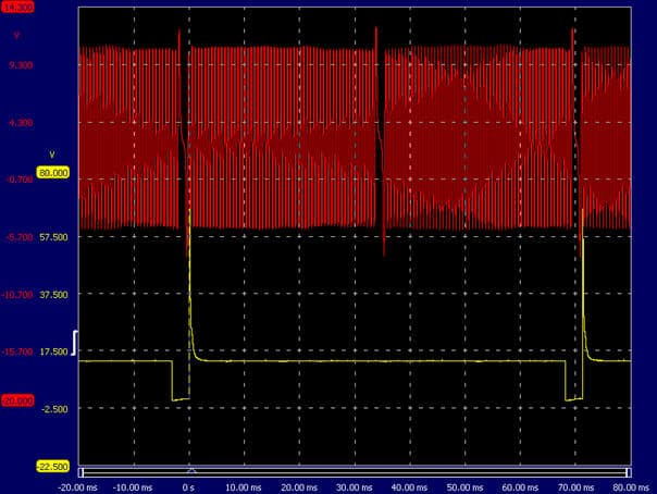
In the next scope pattern, the inductive crankshaft signal is shown in red and the injector signal in yellow. When the speed is increased to about 3000 rpm, two injector actuations can be seen. It is clearly visible that the fuel injection of cylinder 1 takes place with every second crankshaft rotation.
Current limiting in the ECU:
As became apparent from the measurements in the paragraph “Measuring voltage and current on a multipoint injector”, there is a delay between actuating and actually opening the injector needle. In this case, it takes 1.5 ms to open.
The injector needle would open faster if the current through the coil were to rise faster. The current strength depends on the resistance of the coil: the lower the resistance, the faster the current build-up. The high-impedance injectors used in the engine of the measurements have a resistance of 16 ohms. At a board voltage of 14 volts, a small current will flow:
The current strength is sufficient to open the injector needle, but not so high that it would become too hot due to excessive power:
Because only a low power is generated, it is not necessary to use current control. This would be necessary with low-impedance injectors.
- Low-impedance injectors have the advantage that the current build-up is already rapid from the start. This results in a fast opening of the injector needle, so little delay.
- Low-impedance injectors have a resistance of about 2.8 ohms. Due to the low resistance, a high current flows:
The power also increases sharply:
The power consumption is almost seven times higher than with high-impedance injectors. If the current becomes too high, heat develops in the injectors and in the output stage of the control unit. To limit the current, the voltage is switched on and off several times in a short period. After the injector needle has opened, little energy is needed to keep the needle open. During switching on and off, the current decreases. This profile can be seen in the scope pattern.
Determining the required amount of fuel:
The manufacturer has determined the required amount of fuel in various maps that are stored in the ROM memory of the ECU. The engine management system reads from these maps how much fuel is needed without corrections. This obviously depends on engine speed, temperature and load. The most important maps for determining the correct amount of fuel are explained in this paragraph as the VE table and AFR table.
VE table:
The VE table represents the volumetric efficiency and the air/fuel ratio at each engine speed and intake manifold pressure. Volumetric efficiency is the ratio between the measured amount of air filling the cylinders and the amount of air that would fill the cylinder in a static situation, depending on the engine speed and intake manifold pressure. The values in the table are used by the ECU to determine the actual air mass and thus the degree of filling. With this data, the amount of fuel to be injected is calculated.
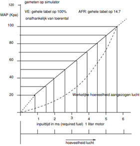
This theoretical approach deviates from reality. At this point, the engine specifications have not yet been taken into account. Consider the valve timing diagram (valve overlap, or possibly variable valve timing), the air resistance in the intake tract, etc. Therefore, a correction factor is applied that indicates a deviation from the linear relationship. The correction factor is shown in the figure above by the dashed line. The curve indicates to what extent the linear relationship is correct. At a pressure of 60 kPa, the deviation is about 50% compared to the line that represents the linear relationship. The correction factor can be expressed as a percentage.
In a VE table, each cell shows the percentage corresponding to the manifold vacuum in relation to engine speed. This percentage will be highest at the engine speed at which the torque is highest. After all, that is where the engine is most efficient because it fills best.
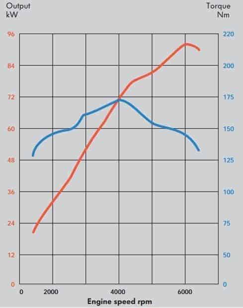
The values in the VE and AFR tables later in this paragraph are derived from the torque and power curves of a 1.8 20v engine from a VW Golf.
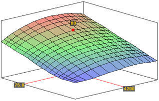
The images below show the VE table as an input table and the three-dimensional view that has been created in the program “TunerStudio” based on the torque and power curves. This program is mainly used to provide a programmable ECU such as the MegaSquirt or Speeduino with software. For more information, see the pages about the MegaSquirt project.
On the vertical axis, the MAP (Manifold Air Pressure) is shown from 15 kPa (high vacuum) to 100 kPa (atmospheric pressure). The MAP indicates the engine load. The horizontal axis shows the engine speed between idle and maximum engine speed.
The cells in the VE table show the volumetric efficiency of the engine. In other words, how efficient the engine is at a given speed and load. Around the speed where the torque is highest (around 4200 rpm), the engine is most efficient; the percentages are highest here. This is where the engine “fills” best. Applying techniques that increase volumetric efficiency, such as variable valve timing, variable intake manifold, or using a turbocharger, will improve these percentages.
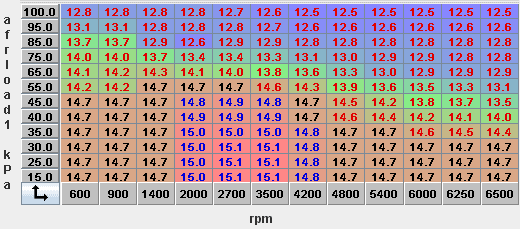
AFR table:
The required air/fuel mixture is defined in an AFR table. AFR is the abbreviation of “Air Fuel Ratio”. With a stoichiometric mixture (lambda = 1) 14.7 kg of air is needed to burn 1 kg of petrol. A stoichiometric mixture is not desired in all situations.
- A lean mixture benefits fuel consumption;
- A rich mixture makes a higher power output possible.
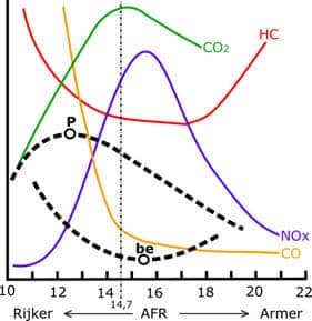
When the engine has to deliver more power (P), enrichment takes place. A richer mixture also provides cooling. Enriching to λ = 0.8 means that an air/fuel ratio (AFR) of 11.76 kg of air to 1 kg of petrol applies. So there is less air available to burn 1 kg of fuel than with a stoichiometric mixture. A lean mixture, on the other hand, gives more favourable fuel consumption (be), but also increases the risk of knocking. Enriching or leaning out the mixture must always remain within the combustion limits.
When idling, the engine speed is between 600 and 900 rpm. The throttle valve is almost completely closed and the vacuum is high: it is between 25 and 40 kPa. In this speed range, the mixture is stoichiometric (14.7:1).
In part-load conditions, the engine speed will have increased to 4200 rpm. The throttle valve is opened further, so the vacuum in the intake manifold drops to 40–75 kPa. With increasing engine load the vacuum decreases; enrichment occurs (AFR of 13:1). At low engine load a lean mixture is possible. At full load the throttle valve is fully opened. The vacuum drops to 100 kPa (atmospheric pressure) and maximum enrichment takes place (12.5:1).
The lambda value not only affects power and fuel consumption, but also exhaust gas emissions. A richer mixture results in a lower NOx content, but also in higher CO and HC emissions. With a leaner mixture, the fuel particles are further apart, so combustion is no longer optimal; as a result, HC emissions also rise.
When using a catalytic converter, it is desirable for the injection to alternate constantly between rich and lean. With a rich mixture, CO is formed as a result of an oxygen deficit, with which the catalytic converter reduces NOx. A lean mixture contains an excess of oxygen, with which CO and HC are oxidised.
The control unit determines how much fuel must be injected. First of all, the basic injection data is read from the maps. The values from the VE and AFR tables, among others, are included in the calculation of the injection quantity. Account is also taken of the following values set by the manufacturer:
- enrichment depending on coolant and intake air temperature;
- short-term acceleration enrichment when the throttle valve is (quickly) opened;
- correction for variations in the on-board voltage.
In addition to these preset values, close attention is paid to the voltages that the lambda sensor sends to the control unit. These voltages depend on the oxygen content in the exhaust gases. This is a variable factor that changes continuously. The input from these sensor voltages is processed as so-called “fuel trims”.
How the values in the VE and AFR tables and the other mentioned settings are determined is described on the pages of the completed MegaSquirt project.