Introduction:
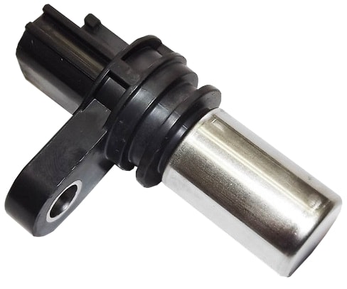
The crankshaft position sensor (also called the TDC sensor or engine speed sensor) is usually mounted at the bottom of the engine block at the height of the flywheel. When the engine is running, the crankshaft position sensor reads the teeth or magnets of the pulse wheel that move past the measuring element of the sensor. With the crankshaft position sensor, a change in the magnetic field between the sensor and the pulse wheel results in a change in the signal voltage (inductive or Hall). The rate at which these pulses follow each other is an indication of the engine speed. At a certain point, one or two teeth of the pulse wheel are missing. The resulting signal indicates to the engine engine control unit the position in which the pistons are located. The engine management uses this to determine, among other things, the injection and ignition timing. The crankshaft speed is also transmitted to the tachometer in the instrument cluster.
Positioning of the sensor and the pulse wheel:
The pulse wheel (also called the trigger wheel, reference wheel or reluctor wheel) can be fitted in or on the engine in several locations:
- externally on the crankshaft pulley: on older engines we see that the crankshaft pulley, which drives the V-belt or multi-ribbed belt, is fitted with teeth. On modern engines we no longer encounter this type of external pulse wheels;
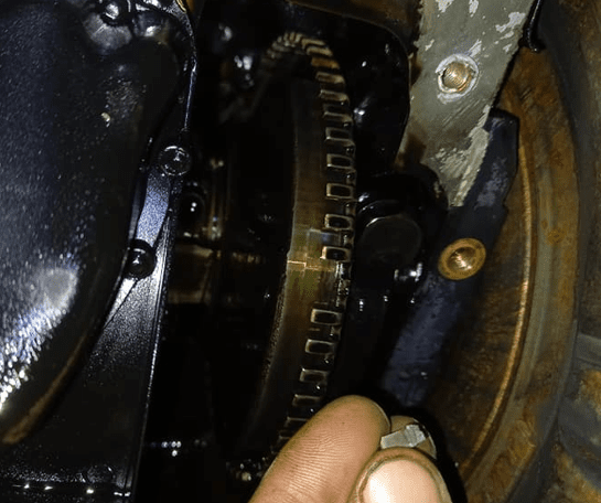
- internally by means of ground teeth on the crankshaft: the pulse wheel is located on the crankshaft on the inside of the crankshaft flange and can be seen when the oil pan has been removed;
- externally at the position of the rear crankshaft seal: on the outside of the engine block, between the outer side of the crankshaft flange and the flywheel, a toothed ring or magnetic ring is fitted. This can be accessed when the flywheel has been removed.
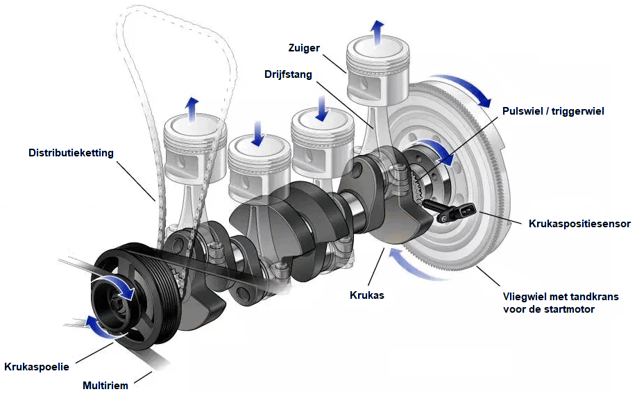
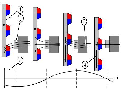
The crankshaft sensor is aimed at the pulse wheel. On modern engines the crankshaft sensor is usually located on the side of the engine near the flywheel. The images below show three different installation positions of the crankshaft position sensor and pulse wheel: teeth on the crankshaft on the inside of the flange, and on the outside of the flange a magnetic ring and a toothed ring.


The images above show pulse wheels with crankshaft position sensors used by VAG and BMW. The version often used by VAG consists of a cassette in which the toothed pulse wheel also houses the crankshaft oil seal. The magnetic ring from BMW is slid over the crankshaft flange. When replacing the flywheel, care must be taken that this magnetic ring does not fall out. It happens more often that after replacing the clutch including flywheel the engine will no longer start because the magnetic ring has not been reinstalled.
The missing tooth in the pulse wheel:
The crankshaft position sensor measures the teeth on the reference wheel, which is mounted on the crankshaft. The crankshaft position sensor “counts” the teeth that pass by and “notices” that in every revolution one tooth is missing. Based on this missing tooth, the engine management system knows in which position the crankshaft is, and thus also at what height the piston is in the cylinder during the compression stroke.
The missing tooth is positioned at the point where the piston of cylinder 1 is between 90 and 120 degrees before TDC. The term “TDC sensor” is therefore incorrect: the sensor does not measure the point when the piston is at TDC, but the position in which the piston is on its way to TDC.
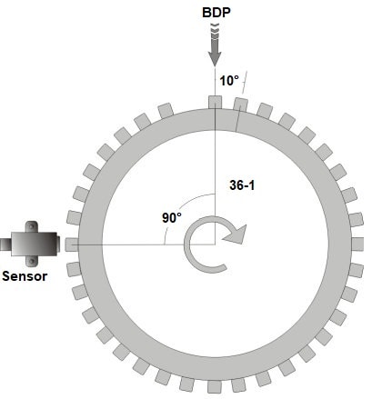
Many engines are equipped with a 36-1 or a 60-2 pulse wheel. In this example we discuss the 36-1 pulse wheel. This pulse wheel has 36 teeth, one of which has been ground off. Every crankshaft rotation (360°) therefore passes 36 (minus the missing) teeth. This means that every 10° one tooth passes the sensor.
In the image we see that the missing tooth is almost at the top. In this position the engine is at TDC. The direction of rotation is clockwise, so 90° earlier the missing tooth passed the sensor. This position is the reference point. In this 90° rotation the piston of cylinder 1 has moved from BDC to TDC.
At the moment the missing tooth passed the sensor, the sensor translated this into a change in the crankshaft signal, and this was the recognition point (reference point) for the engine management system to start injecting and/or igniting a number of teeth later.
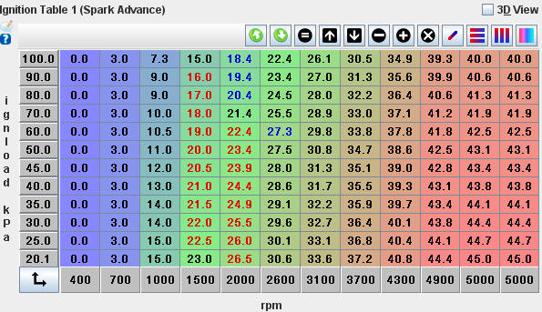
When the engine speed or engine load increases, we refer to “pre-injection” or “ignition advance“. This is possible using the reference point at 90 or 120° before TDC. Example regarding the ignition timing:
- At low speed and low load (1000 rpm at 25 kPa) the ignition advance is 15°. This corresponds to one and a half teeth before TDC;
- At increased speed and increased load (3100 rpm at 60 kPa) the ignition advance is almost 30°. This corresponds to three teeth before TDC.
At the moment when, in the latter situation, ignition must occur three teeth before TDC, the engine management system has the time between the 9 teeth (90°) from the reference point and three teeth (30°) from the desired ignition timing to control the ignition coil, so that the ignition is initiated before the piston has reached TDC.
A crankshaft position sensor sends a signal from which the engine management system can deduce that the piston of cylinder 1 is in the position 90° or 120° before TDC. What is not known is whether the piston is in the compression stroke or the exhaust stroke.
- An engine with only a crankshaft position sensor is fitted with a DIS coil, in which every crankshaft rotation all spark plugs fire, and there is therefore a “wasted spark” during the exhaust stroke;
- For individual control of pencil coils and injectors, a camshaft sensor is required. Using the information from the camshaft sensor, the engine management system can determine that cylinder 1 is in the compression stroke and not in the exhaust stroke.
With the combination of the crankshaft and camshaft sensor, the engine speed and the control of the injection and ignition system per cylinder are achieved.
Operation of the crankshaft position sensor:
In the bottom left image the magnetic field lines can be seen that arise when a tooth of the crankshaft moves past the magnet of the crankshaft position sensor. In the bottom right image the crankshaft signal can be seen. At each missing tooth on the crankshaft, an increased distance in width and a higher amplitude of the signal can be seen. The increased width in the signal is recognised by the engine management system as the reference point, at which the piston is at 90° or 120° before TDC.
Electrical diagrams crankshaft position sensor:
To measure the crankshaft position sensor, we first consult the electrical diagrams. The diagrams below are of the sensor of the same engine (VW Golf VI).
- In the VAG diagram the crankshaft position sensor has the component code G28 and in HGS-data B56);
- The VAG diagrams use the coding T60 on the ECU followed by the pin number of the connector (T60/25) and HGS-data uses the letter B (B25). Elsewhere in the diagram it is stated that connector B is the 60-pin connector on the ECU).
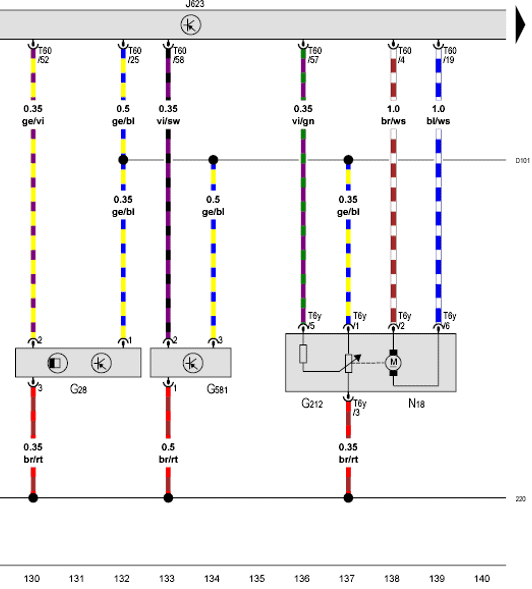
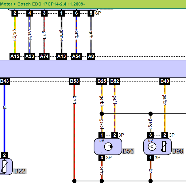
From pin 25 on the ECU, a 5-volt supply voltage is sent to the crankshaft position sensor, fuel pressure sensor, EGR valve, throttle valve and the position sensor of the turbo actuator. Not all components are shown above. So pin 25 is used for the power supply. Pin 53 for the ground (as can be seen in the HGS-data diagram) and pin 52 for the signal from the crankshaft position sensor. We can measure directly on pin 52 in the ECU connector, or we can connect a breakout box to measure safely and clearly at connection 52 of the breakout box.
Measuring signals with the oscilloscope:
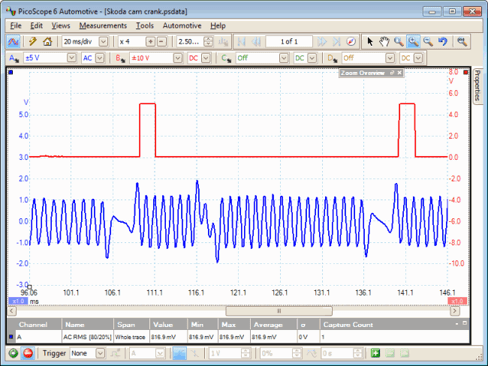
The crankshaft signal can be displayed with a two-channel measurement in relation to the camshaft signal. Using these signals, it can be determined whether the timing of the valve train is still correct, or whether the camshaft signal is, for example, lagging behind the crankshaft signal due to a stretched timing chain. The image below shows a measurement of a crankshaft signal (channel A, blue) in relation to a camshaft signal (channel B, red).
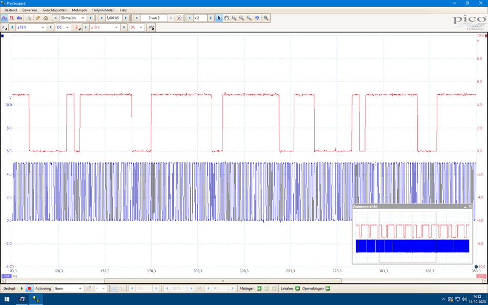
In the signals from the crankshaft and camshaft sensors we can identify the following points:
- With every camshaft rotation (reference points: the two narrow blocks) four missing teeth of the crankshaft have passed by;
- The crankshaft makes two rotations while the camshaft makes one (ratio 2:1), which means that every half rotation of the crankshaft one missing tooth passes the sensor.
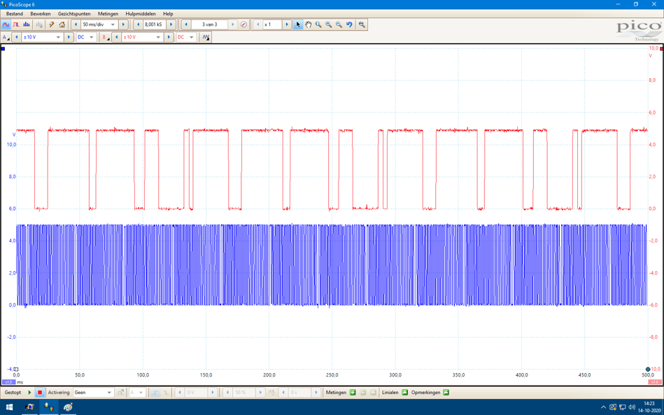
The engine in this example (VW Golf VI) is equipped with a toothed pulse wheel with a missing tooth every 180 degrees (half revolution). This pulse wheel is shown in the image in the paragraph “Positioning of the sensor and the pulse wheel”. If you look closely, you can identify the missing teeth in this image. When the engine speed is increased, the frequency of the signal also becomes higher. The pulses then move closer together. The amplitude (the height of the voltage) remains the same. A measurement on the same engine at an increased engine speed can be seen in the scope image below:
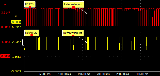
In case of suspected problems regarding the valve timing, reference points in the crankshaft and camshaft signal can be compared with a reference signal or with another engine without problems.
By marking two points, the difference in the number of teeth in the measured signal can be compared with the reference signal. If in the measured signal the crankshaft signal leads the camshaft signal (the reference point of the crankshaft shifts to the left), the timing chain may be stretched.
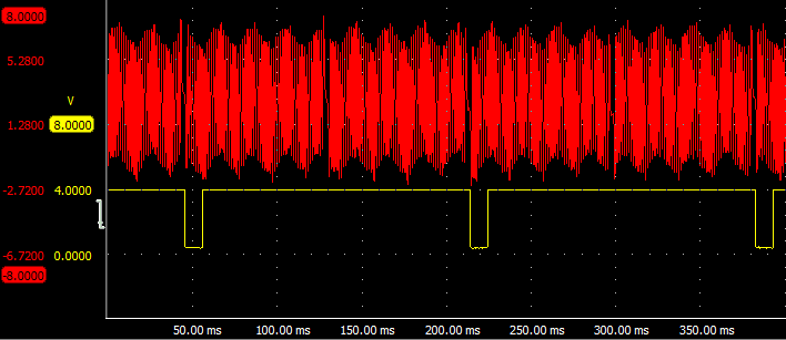
The above crankshaft signal is from a Hall sensor. An engine can also be equipped with an inductive sensor. An example of this can be seen in the measurement below. With an inductive sensor, when the engine speed is increased not only does the frequency increase (the pulses move closer together), but the amplitude also becomes higher. For the ECU the frequency is important to determine the engine speed. In this signal as well, the missing tooth is clearly visible. The yellow line (coming from the camshaft sensor) sends a pulse after every second crankshaft signal. These signals can again be compared with each other.
With the inductive crankshaft signal a reference point can also be chosen, e.g.:
- the camshaft signal drops to 0 volts;
- this happens two (crankshaft) teeth after the missing tooth.
In a reference signal, you check whether there are also two teeth in between. If there are three teeth in between, there is again a deviation.
Possible faults in the crankshaft sensor signal:
The crankshaft sensor can be defective and output no signal. The engine management system will not receive an engine speed signal, causing the engine not to start while cranking. The camshaft signal may be picked up and the engine may run – after extended cranking – on the camshaft signal alone.
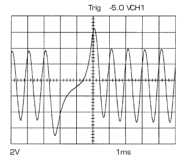
With a damaged pulse wheel, the engine management system may incorrectly recognize the damage as a missing tooth. After all, the damage causes a deviation in the amplitude of the AC voltage supplied by the crankshaft sensor. An example can be seen in the images below.
In the scope image, we see twice the characteristic pattern of the missing tooth (to the left in relation to the camshaft pulse). To the right of the camshaft pulse we see a disturbance in the image. The engine management reads the disturbance and may therefore start injecting and igniting at the wrong moment. When the EMS compares the crankshaft signal with the camshaft signal, a fault can be detected and a DTC (fault code) stored relating to the crankshaft signal. In this case, the crankshaft position sensor may be wrongly replaced.
The damaged tooth on the pulse wheel may have been caused by work on the engine, where someone tried to lock the crankshaft with a screwdriver between the teeth of the pulse wheel instead of the starter ring gear on the flywheel.