Engine management with self-diagnosis:
Every modern car has engine management. This is the name for the software that is implemented in the ECU (Electronic Control Unit). All sensors and actuators mounted on the engine are connected to the ECU with wiring looms. Click here for more information about the control units and networks in the car. The main functions of the ECU are controlling the ignition and the injection in order to achieve as little emissions as possible. Around that there are many other functions connected, all of which influence each other. These are discussed below.
The ECU processes the incoming data (from the sensors), processes it and then controls the actuators. An example of a sensor is the lambda sensor. When the lambda sensor measures an excessively high oxygen level in the exhaust gases, it will pass this on to the ECU. The ECU then knows that the mixture is too lean (too little fuel = too much oxygen in the exhaust gases = therefore too lean). The ECU will then adjust the injection and ignition until the lambda sensor gives the correct signal.
When a sensor transmits an impossible measured value (for example, the coolant temperature sensor indicates an immeasurable value), or when it detects that the wiring has a short circuit to positive or ground, the ECU will automatically store this as a fault code. The advantage of the advanced software is that the incorrect signal is blocked internally. The ignition and injection, for example, are not adjusted according to the wrong temperature, because the ECU has already recognized that this signal is incorrect.
However, the ECU will drive the cooling fan at full speed because the correct temperature can no longer be measured. As a precaution, extra cooling is provided. A yellow engine warning light will then illuminate on the dashboard. The car will then need to be read out. Click here to go to the OBD page where a lot of explanation is given about reading out faults and other possibilities of the diagnostic equipment.
Another example is an ignition coil that has failed. The fuel will enter the catalytic converter unburned and may still combust there due to the high temperature. The crankshaft sensor will register a fluctuation in engine speed due to the misfire. The position of the misfiring cylinder is recognized. As a result, the injector of the cylinder with the defective ignition coil is no longer actuated. The engine is now in limp mode and will run with one cylinder less. The engine warning light will come on. Reading out the ECU will show which cylinder is misfiring.
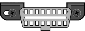
To read out the ECU, the diagnostic connector of the computer (in the picture) is connected to the OBD connector. This OBD connector is usually located at the bottom of the dashboard near the footwell (near the pedals). The connector can also be hidden in other places in the dashboard or behind ashtrays. By connecting the plug to the diagnostic computer, the fault codes are transmitted to the computer.
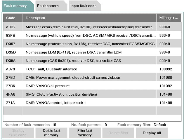
When the car is read out, the ECU will send a fault code to the diagnostic computer. This fault code (OBD fault code) is often the same for each brand. These codes can be displayed with a scan tool. The fault code is stored by the ECU and it also stores the following information:
- When the fault first and last occurred.
- How often the fault has reoccurred.
- Whether it is a permanent or an intermittent (sometimes recurring) fault.
Fault codes are not always the same for every brand. Sometimes the codes are brand-specific. By searching for the fault code in Google, the meaning can often be found.
Advanced diagnostic equipment links text to this fault code. In fact, the code is then translated into text. For example, code P0267 will be linked to the text: “Coolant temperature sensor implausible signal; short to positive.” First occurred at mileage ……km, frequency 120, sporadic occurrence. It is now clear that either the sensor has an internal defect, or the signal wire of the sensor is shorted to a positive wire. This has happened a total of 120 times and is not permanently present. This may mean that due to movement of the cables, the short circuit has occurred 120 times and then disappeared again. It is up to the mechanic to find out where the fault is located.
When the fault has been rectified (e.g. after repairing the cable) the fault can be cleared. A code is then sent to the ECU with the test equipment, which then understands that the fault must be erased from memory. If the cable is not repaired but only the fault is cleared, the fault will immediately return. After clearing, the first occurrence mileage will be the current mileage and the frequency will start again from 1.
Control functions and operation of the engine management:
The task of the engine management is to monitor or control, among other things, the following functions:
- Engine speed
- Vehicle speed
- Position of accelerator pedal / brake pedal / clutch pedal
- Ignition
- Injection
- Variable valve timing
- Variable intake manifold
- Alternator control (DF signal)
- Mass air flow sensor signal
- Throttle valve position
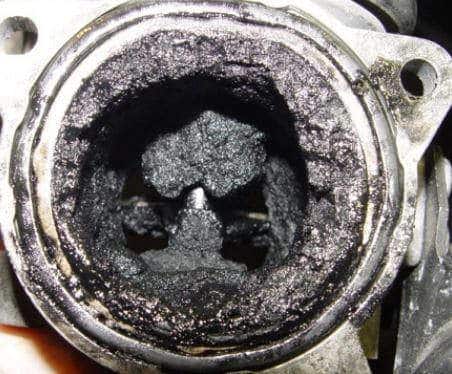
- EGR valve position
- Crankshaft / camshaft position
- Temperature control via the map-controlled thermostat
- Knock control
- Lambda control
- Electronic coolant pump
- Evaporative emission control (tank venting)
- Fuel pump (lift and high pressure)
- Cruise Control
- Crankcase ventilation heating
- Oil level monitoring
- Turbo pressure
- Intake manifold pressure
- Energy management (battery state-of-charge sensor)
- Communication with automatic transmission (reducing engine power during gear changes in an automatic transmission)
- Self-diagnosis (including storage of fault codes)
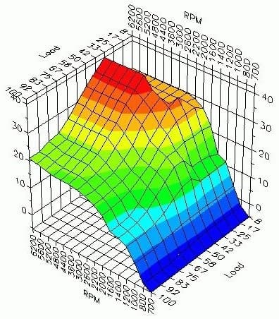
All incoming signals are processed in a map (see the image above). The map will process the input signals (from the sensors) on the basis of, among other things, engine speed and load, the ambient air, coolant, engine oil and exhaust gas temperatures. With this data, the map determines what the output will be, i.e. how an actuator will be controlled, for example. For a cold engine, more fuel must be injected (cold start enrichment) to keep the engine running. In the past, this was done with a manual choke, but with engine management this is all controlled automatically via the VE and AFR tables. These tables represent the volumetric efficiency and air-fuel ratios.
The ambient temperature and coolant temperature are measured and, when the engine is running, the ignition timing is determined using the knock sensors and the speed sensors are used to determine whether the engine is running smoothly. The throttle valve will also be commanded more “open”. After a certain period of time, the temperature in the combustion chamber will be high enough to switch to normal injection.
When the engine is in the warm-up phase as just described, this is called “Open Loop”. The feedback from the lambda sensor is not used. The lambda sensor measures a mixture that is far too rich (during cold start enrichment) and would therefore actually want the engine to run leaner. But because enrichment is necessary, the data from the lambda sensor is ignored. When the engine has reached sufficient temperature, the incoming signals from the lambda sensor will be used again. This is then called “Closed Loop”. In short: the ECU determines which signals are or are not used.
The different maps are described on the injection system page.
Adaptive memory:
The engine management software contains a so-called “adaptive learning memory”. In this, the actuators are controlled on the basis of previously received data from the sensors. This takes into account some wear and contamination of the engine. For wear, think for example of a lower final compression pressure, causing the idle speed to be lower than with a new engine. The engine management software must respond to this by adjusting the fuel trims.
Among other things, the data of the opening and closing of the throttle valve is stored in the adaptive memory. Over time, the throttle valve becomes contaminated due to the influence of the EGR and crankcase ventilation fumes. Opening and closing the valve becomes a bit more difficult and with contamination the valve has to open slightly further, otherwise the carbon deposits will block the air passage. The control strategy for an older engine will therefore be different from that of a new engine. Without adaptive memory, the control would have to search for the correct values again every time the engine is started. With adaptive memory, the engine management software takes this into account.
After cleaning the throttle valve or EGR valve, for example, it often needs to be relearned. During relearning, the adaptive memory is reset. After relearning, the engine management will again check and store the values of the sensors. After relearning, it may therefore happen that the engine runs a bit unevenly and shakes.
A lambda sensor becomes slower as it gets older. The data does reach the engine management, but by means of the adaptive memory the engine management takes into account the ageing of the lambda sensor. It is therefore important to erase the adaptation values after the lambda sensor has been replaced.
The automatic transmission contains clutches that are actuated by oil pressure to shift gears. Older transmission oil is often more contaminated and thicker than new oil. Engine speeds and shift points will therefore be different with new oil than with old oil. The automatic transmission also contains a control unit with adaptive memory, which has adjusted the shift points as ideally as possible over time. After the oil has been changed, the shifting behaviour can become very different. Think of incorrect engine speeds for shifting to higher or lower gears, or abrupt engagement of gears causing a jolt in the drivetrain. That is why, after changing the oil, the adaptation values of the transmission must also be erased.
Often, an adaptation drive must be performed after the adaptation values have been erased. The vehicle must then be driven at as many different engine speeds and road speeds as possible, so that the system has the opportunity to calculate and store the adaptation values correctly.
The origin of a fault code:
A sensor can be defective. The wiring or connector of the sensor can also become faulty, disrupting the connection between the sensor and the ECU. The ECU therefore receives incorrect values from the sensor. In the past, this could affect the operation of the engine; a defective temperature sensor could cause far too much fuel to be injected, causing the engine to “flood”. This risk is much smaller nowadays. The engine management can recognize that the value from the sensor is incorrect.
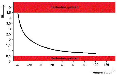
In this example, the voltage curve of a temperature sensor is shown. The temperature is represented by voltages between 0.5 and 4.5 volts. Voltages lower than 0.5 V and higher than 4.5 volts are in the forbidden area. The voltages can be seen in the graph below. When the sensor is defective, or a cable has a short circuit to ground, a voltage of 0 volts is transmitted. This lies in the forbidden area. The ECU recognizes this and stores a fault code.
Not only is the fault code stored, but the signal is also not used. The ECU switches to a limp-home situation; a substitute value is calculated from other data received by the ECU. The substitute value is close to the actual value, so it is still possible to drive to the workshop. Of course, the intention is not to ignore the fault, because for example the fuel consumption can increase considerably.
Adjusting the software:
The software in the ECU can be adjusted with suitable equipment. And of course the necessary expertise, because incorrect programming can cause serious damage to the engine. Rewriting the software can be done by a software update from the manufacturer (to correct errors discovered later) or by tuning. This increases the engine power by adjusting the map in the ECU. More information on this can be found on the chiptuning page.