Instrument panel:
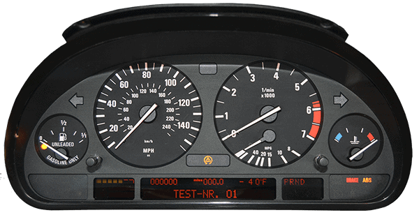
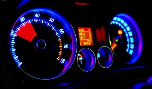
In almost every dashboard, an instrument panel is installed. This can be either analog (with moving needles) or (partially) digital. The instrument panel contains the gauges (tachometer, coolant temperature gauge, fuel gauge, speedometer), the clock and odometer, the warning lights for the airbag, ABS/ASR, coolant level / oil level light, handbrake warning light, alternator (battery) light, etc.
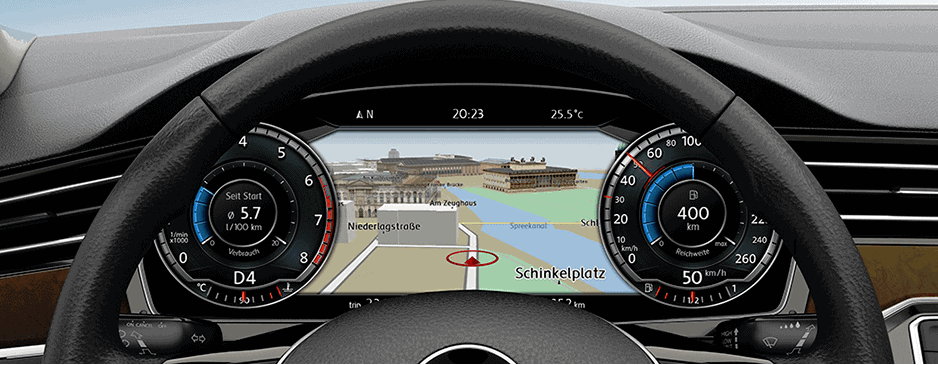
The instrument panel in the image below also has an on-board computer built in. This shows the engine oil temperature, fuel consumption, average speed, a stopwatch, etc. The on-board computer display can also show RDS information (the radio stations and RDS text are displayed there).
In many cars the immobilizer is also programmed in the instrument panel. If the transponder in the key is not recognized, the engine will not start. Only when the code transmitted by the key is recognized by the immobilizer in the instrument panel can the car be started. This is an anti-theft protection and is also called a class 1 (alarm/security) system. The immobilizer light is also illuminated in the image below (the car with the key at the top right). The keys must be programmed with a diagnostic tool via the OBD connector.
Indicator lights:
There is often a lot of uncertainty about the meaning of the indicator lights that can light up in the instrument panel. Below are many common lights that can come on with their meanings and possible causes:
ABS: Malfunction in the ABS system (possibly in a sensor, wiring, or control unit).
Battery: Possible fault in the alternator. This light will always be on when the ignition is on and the engine is off. As soon as the engine is started, this light goes out if the system is working correctly.
Rear window defogger: This light is usually not displayed in the instrument panel, but on the rear window defogger switch.

Airbag: This light indicates a fault in the airbag system. There may be a problem in the wiring, an airbag component, a crash sensor, or the control unit.
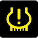
General warning: This light is usually accompanied by a text warning such as: close the door before driving off, etc.
Cruise Control: The cruise control light can also be green or red (depending on the make). The light will illuminate when the cruise control is switched on or off.
Lighting warning: The system has detected a defective bulb. The driver must check which bulb is faulty.
Door signal: One or more doors are open.

Hazard lights: This symbol is always on the hazard light switch, which must be used in situations where other road users need to be warned of a potentially dangerous situation.
Glow plug warning light: In a diesel engine this symbol is displayed when there is a problem with the preheating system. In some models from the VAG group this light will also come on if the brake light switch is defective, or if all brake light bulbs on the car are defective.
Seat belt warning: When the driver or passenger does not fasten their seat belt, the light will come on (possibly in combination with an audible signal).
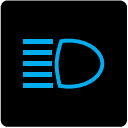
High beam: This warning light comes on when the high beam is switched on.
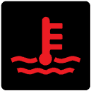
Engine cooling: The engine’s cooling system is overheating; possibly due to a low coolant level, a lack of cooling caused by a defective cooling fan, or a faulty sensor.
Tire pressure: This light comes on when the tire pressure monitoring system has detected a flat tire. This light can also be red (depending on the make). Stop the car at the first opportunity to check the tire pressure and perform or have a repair carried out, or to fit the spare wheel.
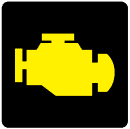
Motor Indication Lamp (MIL): The MIL lights up when an engine fault has been stored. It can also illuminate together with an EPC (emissions) light.
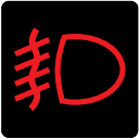
Rear fog light: The rear fog light indicator must be illuminated on the switch or in the instrument panel when it is switched on.
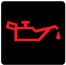
Oil pressure warning: If the oil can symbol is red, there is a problem with the oil pressure. Switch off the engine immediately to prevent engine damage. Possible causes include: low oil pressure due to a defective oil pump, clogged lines / strainer, an oil level that is far too low, etc.
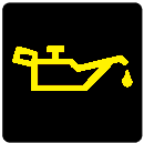
Oil level warning: With a yellow oil can symbol, the driver is warned of a low oil level. The level will be at or below the minimum mark and must be topped up as soon as possible.
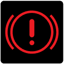
Brake system: The light has multiple functions; as an indication of the applied handbrake, as a warning of a low brake fluid level, and as a warning of worn brake pads.
Turn indicators: One of the arrows will light up when signaling a turn.
Fuel level warning: When the fuel warning light comes on, the fuel level is very low. With the fuel light on, we also speak of the “reserve”, which usually amounts to around 5 liters of fuel. Refueling must therefore be done very soon.
Anti-Slip Regulation: The ASR / DSC is switched off. This may be due to a fault or because it was manually switched off.
Transmission fault: There is a fault in the automatic transmission (gearbox). Possible causes include a low oil level, worn clutches, or worn brake bands, causing internal slip to be detected.
Windscreen defogging / heating: In the case of a fogged-up or frozen windscreen, it can be heated to obtain a clear view.
Tachometer:
The tachometer is a component in the instrument cluster and indicates the number of ‘revolutions’ made by the engine. The revolutions per minute are measured at the crankshaft and registered by the crankshaft position sensor. When accelerating or releasing the throttle, the gauge will display the crankshaft speed, i.e. the engine speed. When the gauge shows e.g. 30, this must be multiplied by 100 (often x100 is indicated as well). That means the engine is making 3000 revolutions per minute. When this 3000 is divided by 60 (3000/60), the result is 50 Hz (Hertz). The engine is then running at 50 rotations per second. In this way, any engine speed can be divided by 60 to calculate the rotational speed of the crankshaft in seconds.
Digital or analogue input for the tachometer:
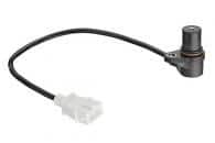
In modern cars, the crankshaft speed is measured by an impulse sensor. On the flywheel a specific part is always recognized (by a wide or missing tooth on the ring gear) which rotates past the sensor during each revolution of the crankshaft. Every time this part passes the sensor, the sensor detects that the crankshaft has turned one revolution. The sensor measures the number of revolutions in a certain period of time and sends this to the engine control unit and to the tachometer in the instrument cluster.
Click here for more information about the crankshaft position sensor, where the operation of both the inductive and the Hall sensor is explained using oscilloscope images.
Cars up to the 1990s were not yet equipped with computers and (digital) sensors. Mechanics still predominated. The tachometer was therefore not yet controlled by an ECU. In cars from that era we find the following techniques:
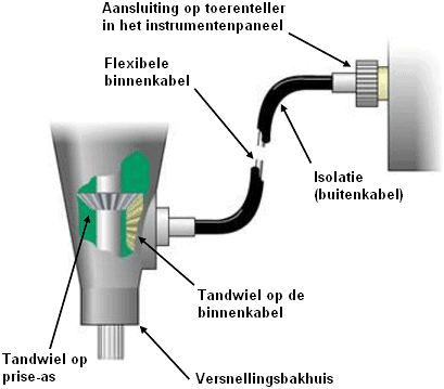
- A mechanical connection between the gearbox and the tachometer: a flexible, rotating cable transfers the movement of the gear in the gearbox to the tachometer. In the gearbox the cable is driven by the input shaft (primary shaft) of the gearbox;
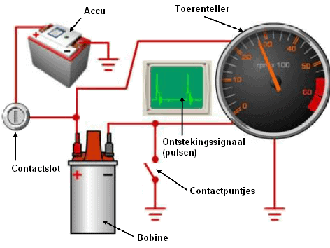
- Electrical signal from the ignition coil: the interruption of the primary winding provides a pulse for the tachometer. The number of alternating pulses per unit of time provides the tachometer with input to indicate an engine speed in revolutions per minute;
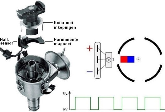
- Electrical signal from the distributor: in the distributor of a conventional ignition system, the rotor rotates to conduct the energy from the ignition coil to the correct spark plug wire. A (rotor) plate with notches is clamped onto this rotor, which rotates past the Hall sensor. The magnetic field between the permanent magnet and the notched rotor plate changes when it turns. The Hall sensor converts this magnetic field into a square-wave voltage. An increasing crankshaft speed, and thus rotor speed, results in a higher frequency of the square signal. The tachometer converts this square signal into an engine speed in revolutions per minute.
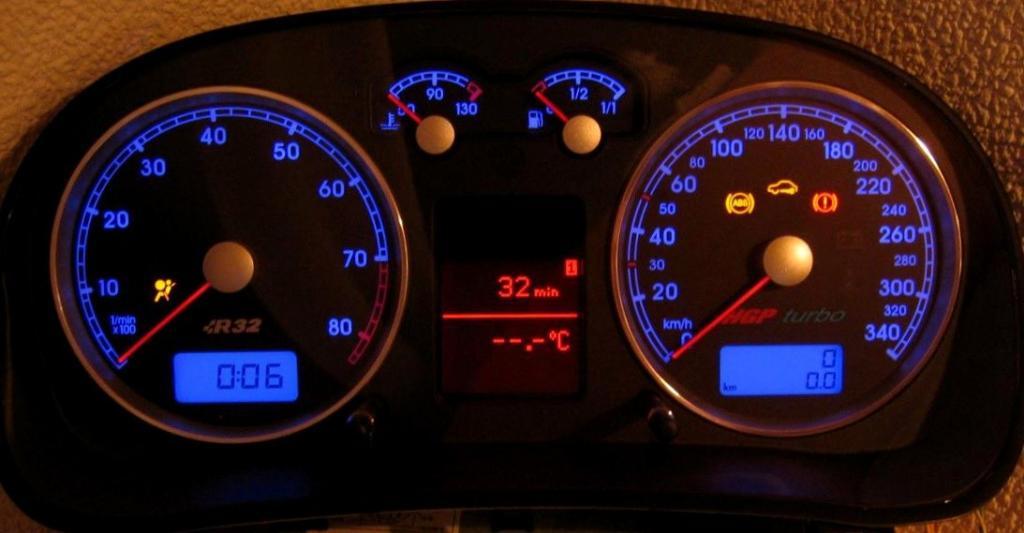
Interactive digital instrument cluster:
In an increasing number of cars, the instrument cluster with analogue needles is being replaced by a digital instrument cluster. This is an LCD screen possibly with a few physical warning lights.
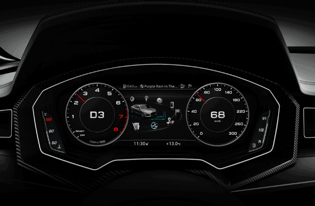
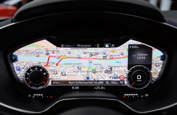
All instruments are fully visualized by software. The image shows the digital instrument cluster of an Audi. Between the tachometer (left) and the speedometer (right) the navigation screen is displayed.
The digital instrument cluster offers many advantages over the conventional analogue instrument panel:
- Navigation maps can be displayed zoomed in and aligned with the driving direction, while the radio / infotainment screen in the center console shows a top-down view. The two navigation displays give the driver a good overview of the route;
- Instead of the navigation maps, images of phone contacts, radio stations, CD covers, night vision, traffic sign recognition and a torque / power meter can also be displayed, among others;
- The display can be individualized to the needs of the driver. Think of the display of the gauges (large / small), a different color, or showing extra functions or, conversely, fewer functions. It is also possible to replace the round gauges with another type of interface, so that the speed is shown only numerically.
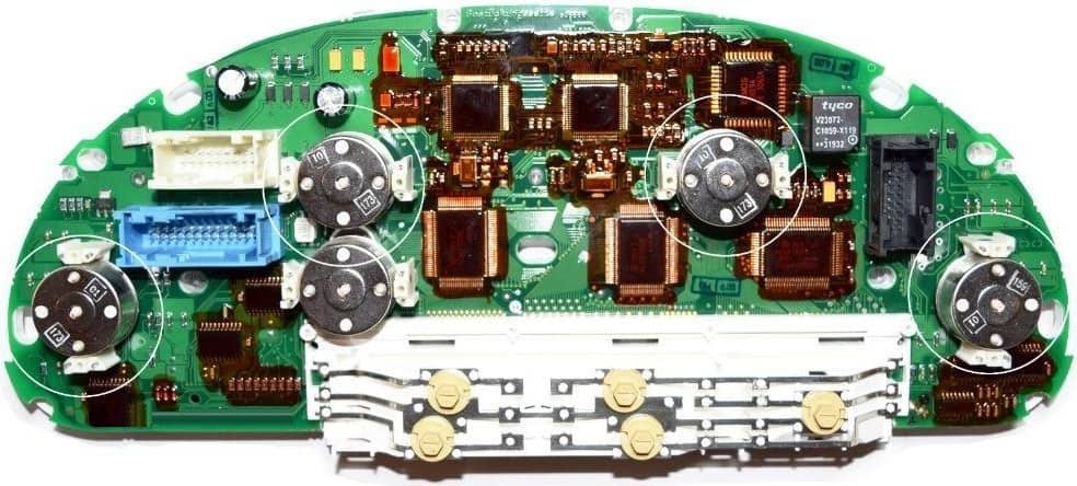
Stepper motor:
An instrument cluster often contains multiple stepper motors to move the needles. In the images below you can see the combination instrument cluster (front and inside) of a BMW. On the page about the stepper motor we go into more depth on the operation and applications of the stepper motor.