Introduction:
As the name suggests, a stepper motor can be controlled in multiple steps. The number of steps can vary. Depending on the application, the stepper motor can adjust from 4 up to 200 steps per rotation, which can result in a controlled rotation starting at 0.8° of rotor rotation.
The angular displacement of a stepper motor can be determined very precisely. A stepper motor is in fact a synchronous DC electric motor without brushes, because the components and control methods have a lot of similarities, but it still differs from this direct current motor due to the following properties:
- A stepper motor has a relatively high torque at low speeds and can therefore accelerate very quickly from standstill;
- The movement of a stepper motor is slow and very precise. The DC motor is used when high speed is needed for a longer period of time;
- The rotational speed and position of the stepper motor are controlled by a control signal from the control unit. Therefore, no position sensor or other form of feedback is required;
- A stepper motor produces more noise and causes more vibrations compared to a brushless DC motor.
The stepper motor is used in many places in the car to enable components to move in a controlled electrical manner. Below are three applications in which the stepper motor is found, namely: for idle speed control, the gauges in the instrument cluster and the heater flaps for ventilation control.
Stepper motor for idle speed control:
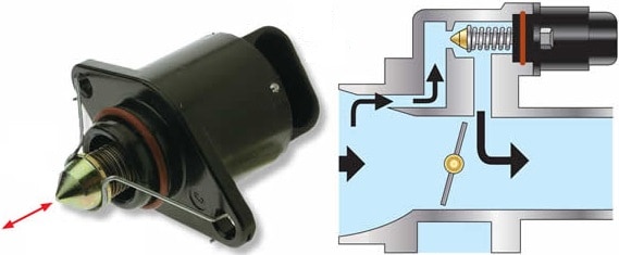
At rest, the throttle valve of a petrol engine is closed. To allow the engine to idle, a small opening is required. The opening must also be adjustable, because temperature and load (e.g. when consumers such as the air conditioning compressor are switched on) affect the required amount of intake air.
In modern engines, the position of the throttle valve is precisely controlled. There are also systems where the throttle valve is completely closed and the air is routed past the throttle via a bypass control. The air bypass can be realised either by a PWM-controlled DC motor or by a stepper motor. See the page about the throttle valve for more information.
The three images below show a stepper motor used as an idle speed controller. The opening of the bypass is controlled by the shaft with the conical end. Rotating the armature in the stepper motor results in a rotation of the worm gear.
- Turning counterclockwise: worm gear rotates inwards (large opening in the bypass);
- Turning clockwise: worm gear rotates outwards (small opening in the bypass).
Instrument cluster:
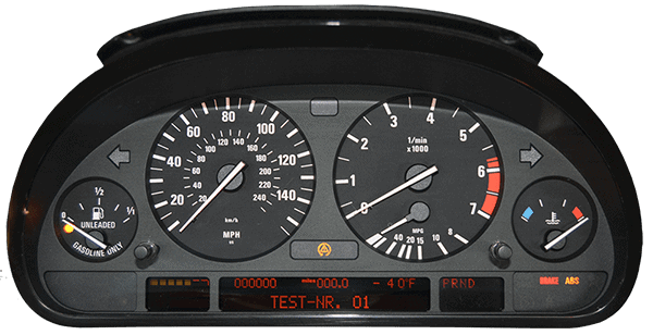
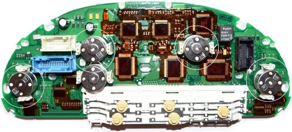
The instrument cluster is often equipped with several stepper motors for the fuel gauge, speedometer, tachometer, engine temperature and, in the example below, also the fuel consumption gauge under the tachometer. Below is an image of the instrument cluster of a BMW.
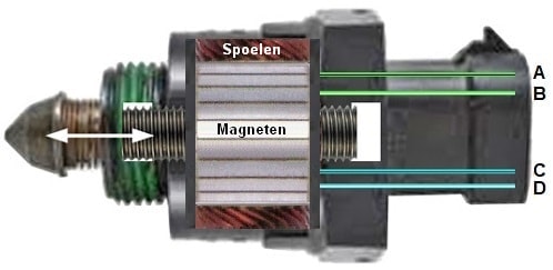
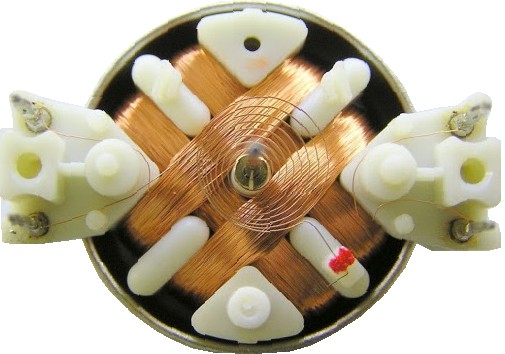
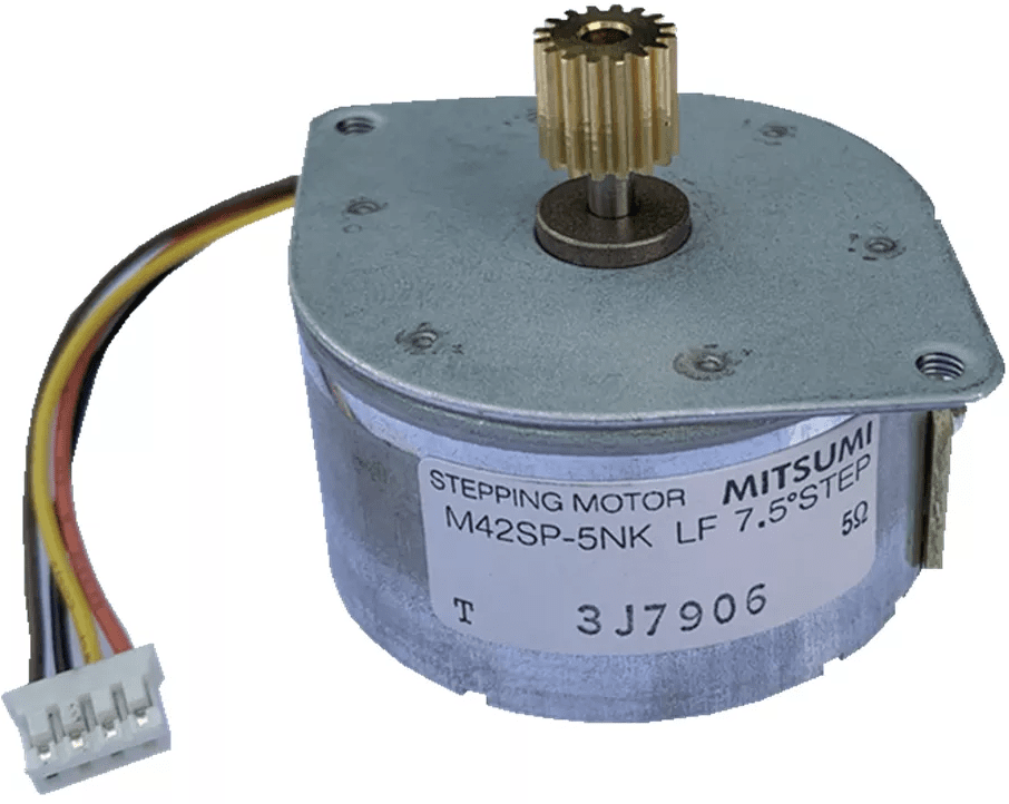
At the rear (inside) of the instrument cluster we find the five stepper motors with black housings. On the right we see the respective stepper motor without housing. The two coils and the four terminals (two on the left, two on the right) are clearly visible, by which we can recognize the bipolar stepper motor. The stepper motor can move the needles in small steps. The command to adjust them comes from the ECU in the instrument cluster.
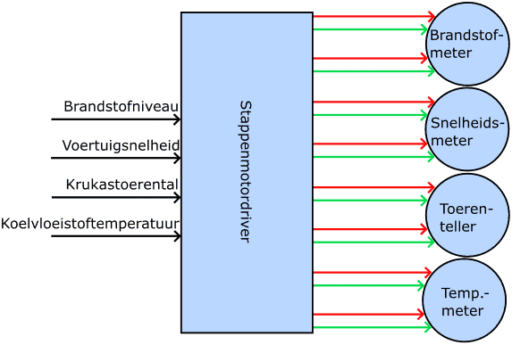
The following diagram shows the inputs and outputs of the stepper motor driver. This is the IC in the instrument cluster that translates the incoming information into an output for the stepper motor:
- fuel level in the tank (fuel sender unit);
- vehicle speed (pulse generator in the gearbox or ABS sensors);
- engine speed (crankshaft position sensor);
- temperature (coolant temperature sensor).
In the block diagram, the red and green arrows indicate the connections (A to D) to the coils in the stepper motor.
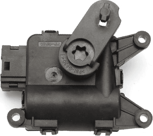
Air distribution flaps in the heater housing:
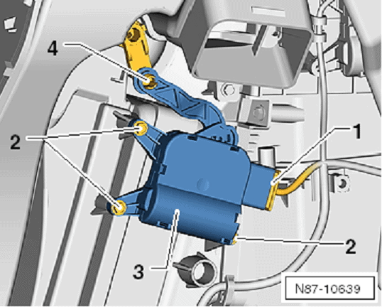
Stepper motors are often used for the electronically controlled air ventilation flaps in the heater housing. The images below show a photo of an air temperature flap (left) and an illustration of the installation position (right). The stepper motor operates the flap via the mechanism in which number 4 in the illustration indicates the pivot point. If the stepper motor does not operate correctly, or after replacement, the ECU must be informed of the start and end positions. With diagnostic equipment we can teach the flap end stops, so that the ECU knows when the flap is fully opened or closed and can thus determine how long it needs to drive the stepper motor to open the flap partially.
Permanent magnet stepper motor (PM type):
This type of stepper motor has a rotor with a permanent magnet. The advantage of this stepper motor is its simple construction and therefore low cost. Below is information about the operation of this stepper motor.
The rotor of the stepper motor can make a full rotation with several intermediate steps. In the example in the four images below, four intermediate steps per rotation are shown. The rotor can therefore be stopped every 90 degrees. The left stepper motor is in position 1, with the north pole of the rotor at the top and the south pole at the bottom. To move the rotor 90 degrees clockwise, the current through the coil with terminals C and D is interrupted and the other coil is energized. This can be seen in the second stepper motor. The left pole shoe turns red (the north pole) and the right one turns black (the south pole). As a result, the rotor will move to position 2.
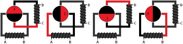
The same principle applies to positions 3 and 4; the coil between C and D is energized for position 3, only the current now flows in the opposite direction compared to position 1. The upper pole shoe is now the north pole and the lower one is the south pole. The rotor will now move to position 3. For position 4, the lower coil is energized again and the rotor will rotate to position 4.
The four-position stepper motor can be stopped every 90 degrees. When this is not sufficient for the application for which the stepper motor is used, it can also be set in eight steps. This is possible with the same stepper motor, only during these intermediate steps both coils are energized simultaneously.
These intermediate steps can be seen in the image below. These are steps 5 through 8. As you can see, position 5 is between steps 1 and 2. The same applies to step 6 (between steps 2 and 3), etc. During these intermediate steps a current flows through both coils.
When the rotor needs to be rotated to step 5, a current flows both in the lower coil from A to B and in the upper coil from C to D. There are now two north poles (the red pole shoes) and two south poles (the black pole shoes). The rotor will move to position 5.
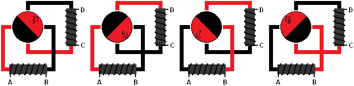
To rotate the rotor a further 45 degrees (to position 2), the diagram of the four-position stepper motor applies again. In that case, the lower coil will be energized again to make the current flow from A to B.
If the stepper motor is then rotated another 45 degrees (to position 6), the image above applies again, in which both coils are energized.
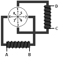
The stepper motor is always controlled by a control unit. The transistors in the driver IC of the control unit provide the current supply and removal to and from the pole shoes. There are eight transistors in the control unit. By controlling these eight transistors in the correct way, the stepper motor will make a full revolution in four or eight steps. The revolution can be made in two directions; counterclockwise and clockwise. The control unit ensures that the correct transistors are switched into conduction.
The image shows a stepper motor that is controlled by a control unit. Transistors 1 and 4 are in conduction. To clarify the control, the transistors and wires are coloured red and brown. Transistor 1 (red) connects terminal A to positive and transistor 4 (brown) connects terminal B to ground.
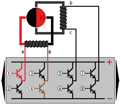
Because transistors 2 and 3 are not in conduction, no current flows through them. If they were, a short circuit would occur.
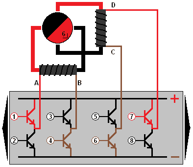
In the image, the stepper motor has rotated slightly further. For this, transistors 6 and 7 must also be switched into conduction.
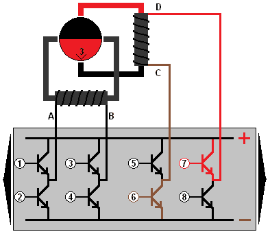
To rotate the stepper motor a little further, conduction of transistors 1 and 4 is stopped. Only transistors 6 and 7 still conduct, causing the stepper motor to assume position 3.
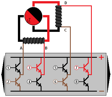
For the next step, transistors 2 and 3 must be switched into conduction.
Variable reluctance stepper motor (VR):
Just like the permanent magnet stepper motor, the variable reluctance stepper motor contains stator poles with coils. It differs from the previously discussed stepper motor by its toothed rotor made of ferromagnetic metal, such as nickel or iron. This means that the rotor itself is not magnetic. This type of stepper motor is nowadays rarely used.
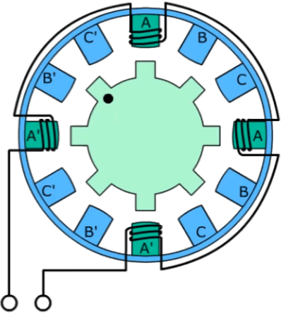
The stator coil on one side (A) is wound in the opposite direction of the coil on the other side (A’). The same obviously applies to B and B’, etc. The teeth of the rotor are attracted by the magnetic flux created when the stator coils are energized.
The advantages of the VR stepper motor compared to the version with permanent magnets are:
- Due to the absence of permanent magnets, production of the VR stepper motor is less harmful to the environment;
- It is not necessary to reverse the polarity of the stator coils. This enables a simpler control;
The disadvantages are:
- Low torque;
- Low accuracy;
- Higher noise level. As a result, the number of applications, including in automotive, is limited;
- Due to the absence of permanent magnets there is no holding torque at standstill.
Hybrid stepper motor:
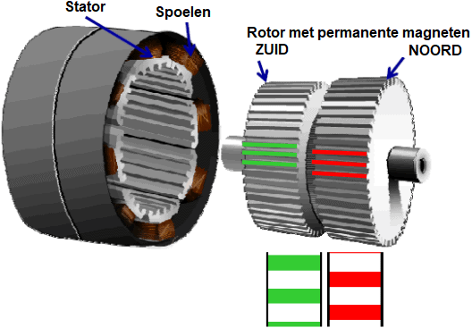
The hybrid stepper motor has a toothed rotor with permanent magnets and a toothed stator with eight coils and a small air gap between the rotor and stator. The rotor consists of two gear wheels that are offset by 3.6° from each other. Inside the rotor there is a large magnet. Two steel gear wheels are pressed over the magnet. Due to the presence of the magnet, the gear wheels also become magnetic. One gear wheel is magnetized as a north pole and the other as a south pole. Each tooth on the rotor becomes a magnetic pole. We therefore speak of the “north pole rotor” and the “south pole rotor”. Because of the offset of the gear wheels, the north and south poles alternate each other during rotation. Each gear wheel has 50 teeth.
When the stepper motor driver allows current to flow through a stator coil, the coil becomes magnetic. The north poles of the coils will attract the south poles of the rotor, causing the rotor to rotate.
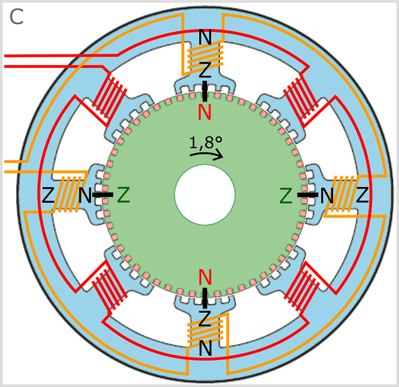
The images below show how the two phases (red and orange) of the hybrid stepper motor are controlled.
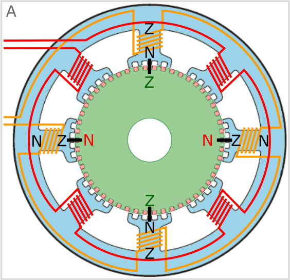
A. The rotor of the stepper motor has rotated to the current position (see the image) because the illustrated coils have been magnetized.
- The green gear wheel is the south pole, which is attracted by the north poles on the stator;
- The teeth between the rotor and the stator are aligned at the points where the rotor has been pulled to. For clarity, these points are marked in black in all three situations;
- The red gear wheel is located behind the green gear wheel. Because the gear wheels are rotated relative to each other, the red teeth are visible. The north poles on the rotor are attracted by the south poles on the stator.
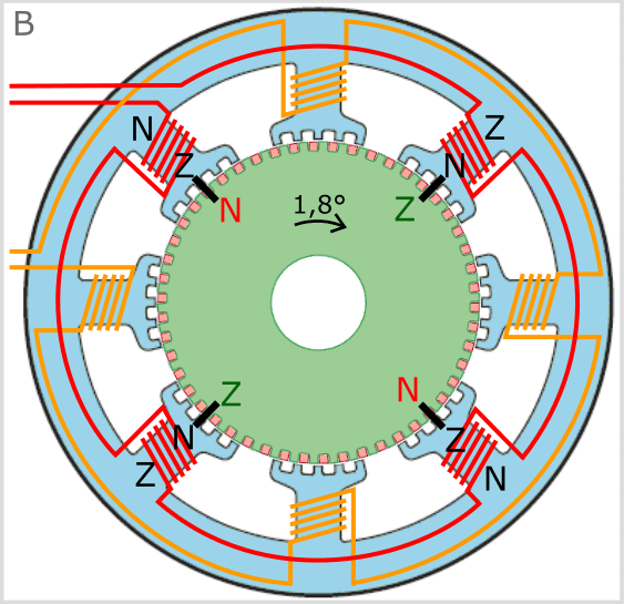
B. The control has switched phase. The magnetic field between the orange coils and the rotor has disappeared. Now the coils of the “red” phase are controlled, building up the magnetic field between the red coils and the rotor.
- As a result of switching the magnetic field from the orange to the red coils, the rotor rotates 1.8° clockwise;
- To rotate the rotor counterclockwise instead of clockwise, the polarity (current direction) through the red terminals would have to be reversed. After all, the direction of the current through the coil determines the direction of the magnetic field and thus the “position” of the north and south poles.
C. The control has switched phase again and the rotor has therefore rotated another 1.8° clockwise.
- The same coils as in situation A are energized, but the polarity on the orange wires is reversed;
- The rotor can be rotated counterclockwise again by controlling the coils as shown in situation B;
- To rotate the rotor clockwise, the red coils are also energized, but compared to situation B the polarity is reversed.
In the examples above, it can be seen that the north pole rotor is attracted by a south-pole coil and at the same time the south pole rotor is attracted by a north-pole coil. This ensures that the hybrid stepper motor makes very precise movements and also has a high torque.
The hybrid stepper motor can be built with more pole pairs and more teeth on the rotor, allowing step angles down to 0.728° and 500 steps per revolution to be achieved.
Related pages: