Introduction:
Every automotive technician, from assistant to technical specialist, has to deal with electronics. In addition to the electronics of comfort and safety systems such as in lighting, the windscreen wiper motor and the ABS system, we find electronics in the control of the engine management system and in the form of communication networks (including CAN-bus). More and more vehicles are also being equipped with an electric driveline. Anyone who wants to understand electronics must start with the basics. In this paragraph we briefly start with an explanation of the electrons that orbit an atom and then fairly quickly move on to electrical diagrams in which the basic concepts of vehicle electronics are explained in a practical way.
Atomic nucleus with electrons:
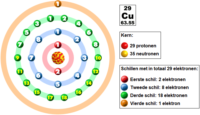
According to Bohr’s atomic model, an atom consists of a nucleus containing protons and neutrons, with electrons orbiting around it in multiple shells. The copper atom contains 29 protons and 35 neutrons in the nucleus.
The electrons are located in four shells. The distribution of the electrons over these shells is called the electron configuration. Each shell has a maximum number of positions for electrons. The first shell (K) has room for two electrons, the second shell (L) for eight, the third shell (M) for eighteen and the remaining shells for 32 electrons.
The electrons in the innermost three shells are bound electrons. The electrons in the outermost shell participate in chemical bonds and reactions and are also called the “valence electrons”. The copper atom contains one valence electron. These electrons can move freely and move to another atom. In the case of copper wire, the outer shells overlap and the single electron can move across the shell of its neighbouring atom.
The relinquishing of the valence electron is important in this context. The jumping of the electron from one atom to another makes it possible for the material to conduct. Materials such as copper, gold and aluminium have a valence electron in the outer shell. Insulators, on the other hand, such as plastic, glass and air, do not have a valence electron. This means that this material is not conductive.
Electron current:
In the following image we see a battery, a lamp, the conductor (copper wire) and a switch. Depending on the position of the switch, current does or does not flow through the circuit. The light blue rectangle represents the copper conductor with the copper atoms (yellow) and the jumping valence electrons (green).
- Switch open: the electrons orbit the copper atom, but there is not yet an electron current flowing through the consumer (the lamp). The lamp does not light up;
- Switch closed: because the battery creates a voltage difference, an electron current flows from minus to plus. The current flows through the lamp and causes it to light up due to the electron current and the voltage difference.
The current moves from – (minus) to + (plus). This is the actual direction of current. In the past, people thought that the current flowed from plus to minus, but that is not correct. Yet for convenience we still adhere to this theory, and call this the “conventional current direction”. From now on we will maintain this conventional current direction, assuming that the current flows from plus to minus.
Current, voltage and resistance:
In this paragraph we will zoom in on the three concepts: current, voltage and resistance. We encounter these concepts time and again in automotive engineering. Current, voltage and resistance each have their own quantity, unit and symbol.
- I = Current = Ampere (A)
- U = Voltage = Volt (V)
- R = Resistance = Ohm (Ω)
Current: In the previous paragraph we looked at the electron current through a circuit. The amount of electrons that flows within one second through a specific cross-sectional area of an electrical conductor is called the current strength. The unit of current is ampere (A). A current of 1 A is reached when 6.24 quintillion (6,240,000,000,000,000,000) electrons have passed through a cross-section within one second. The more electrons that flow within a certain period of time, the higher the current strength.
To gain insight into how much current the electrical consumers in automotive engineering draw, here is a list in which the current is estimated at a charging voltage of 14 volts:
- Starter motor petrol engine: 40 – 80 A;
- Starter motor diesel engine: 100 – 300 A;
- Ignition coil: 3 to 6 A, depending on type;
- Fuel injector petrol engine: 4 – 6 A;
- Electric fuel pump: 4 – 12 A, depending on pressure and flow;
- Electric cooling fan: 10 – 50 A;
- H7 bulb (55 Watt halogen dipped beam): 3.9 A;
- Xenon bulb of 35 Watt: 2.5 A;
- LED bulbs (PWM-controlled and not via a ballast resistor): 0.6 – 1 A;
- Heated rear window: 10 – 15 A;
- Seat heating: 3 – 5 A per seat;
- Standard car radio without on-board computer: ~5 A;
- Windscreen wiper motor: 2 – 5 A, depending on the force;
- Interior blower motor: 2 – 30 A, depending on the speed;
- Electric power steering: 2 – 40 A, depending on the force.
Voltage: Voltage is the force that makes the electrons move. Voltage is a measurement of the difference in force between electrons at two points. Voltage is measured in volts, abbreviated to V. In automotive engineering we work with a “nominal voltage” of 12 volts. That means that the battery and all electrical consumers are based on 12 volts. However, in practice we see that the voltage is never exactly 12 volts, but always slightly lower, and especially often higher. In addition, the voltage in electric drivetrains is many times higher. The consumers in a car consume voltage. As an example we take the heated rear window: this uses a current of approximately 10 amperes at a voltage of 14 volts. The current is not consumed and returns to the battery. The voltage of 14 volts is used in the heated rear window to generate heat. At the end (the earth side) there is 0 volts left.
To gain insight into the possible voltage levels in a passenger car, here is a brief list of voltages that we may encounter:
- Battery voltage: 11 – 14.8 V (almost empty battery to maximum alternator charging voltage);
- Opening voltage of piezo injector: briefly 60 – 200 volts;
- System voltage of a vehicle with an electric drivetrain (hybrid or BEV): 200 – 800 volts.
Resistance: every electrical component has an internal resistance. This resistance value determines how much current will flow. The higher the resistance, the lower the current strength. Resistance is denoted by the letter R and the unit Ohm. As a unit we use the omega symbol from the Greek alphabet: Ω. In an electrical circuit we can add an additional resistor to limit the current.
When a short circuit occurs, for example when a positive wire touches the bodywork, there is a very low resistance. The current then rises rapidly until a fuse blows to prevent damage. The following list shows how much resistance the components we encounter in automotive engineering have:
- Copper wire 2 metres long with a cross-section of 1.25 mm²: 0.028 Ω;
- Lamp (21 Watt incandescent bulb): 1.25 Ω;
- Fuel injector petrol engine (the high-ohm variant): 16 Ω;
- Relay control-current section: ~ 60 Ω;
- Relay main-current section: < 0.1 Ω.
The resistance of a component often depends on the temperature: for example, the resistance of the bulb during operation is much higher than during the measurement when it was cold, in which the current decreases as it becomes warmer.
In summary: the resistance of an electrical component determines how much current will flow. Low resistance means that a lot of current will flow. The supplied voltage (usually around 12 volts) is consumed in the electrical component, resulting in 0 volts on the earth side. Current is not consumed, so it is just as high on the positive side as on the earth side.
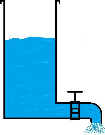
To better understand the concepts, it is sometimes useful to use the example of the water tank. The tank is filled with water and closed at the bottom with a tap. The pressure and the flow of the water through the tap, which allows a certain amount of water to pass, give a good picture of what happens with electricity in a consumer with an internal resistance.
Voltage:
When the tank is filled with water, the water pressure at the tap increases. The water pressure can be compared to the concept of voltage in electricity. The system must be closed, otherwise the water will run out and there will no longer be any water pressure.
Current:
When we open the tap, the water starts to ‘flow’ through the tap. The flow of water can be compared to the concept of current in electricity.
Resistance:
The tap regulates the resistance to the passage of the water flow. As the tap is opened further, the resistance decreases and the flow increases.
The same applies to electricity. With more resistance in the electrical circuit there is less current and vice versa. The resistance has no influence on the voltage.