Topics:
- Introduction
- Measurement without fault
- Diagnosing the sensor wiring
- Fault 1 – Interrupted signal wire
- Fault 2 – Interrupted power wire
- Fault 3 – Interrupted ground wire
- Fault 4 – Contact resistance
- Fault 5 – Short circuit between power and signal wire
- Fault 6 – Short circuit between power and ground wire
- Fault 7 – Short circuit in sensor C
- Fault 8 – No supply voltage due to defective ECU
- Fault 9 – Interrupted PWM signal wire
- Repairing an interrupted power wire
Introduction:
When we suspect there is a fault, we first read out the car. The fault code gives us a direction for further investigation. If no fault codes are stored in the fault memory, we check whether we can detect irregularities in the live data. See the page On Board Diagnostics.
If the fault code relates to a sensor, that does not necessarily mean that the sensor is defective. To rule out any problems in the wiring and/or connector terminals, we use wiring diagrams and measuring equipment to exclude certain possibilities. On this page a number of possible situations are outlined, showing that the description of the fault code can differ from the actual cause.
Measurement without fault:
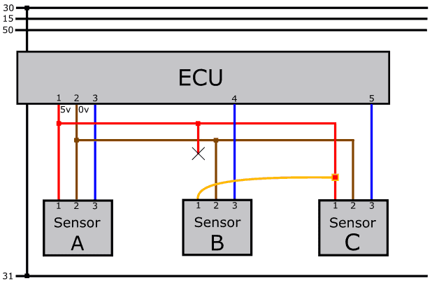
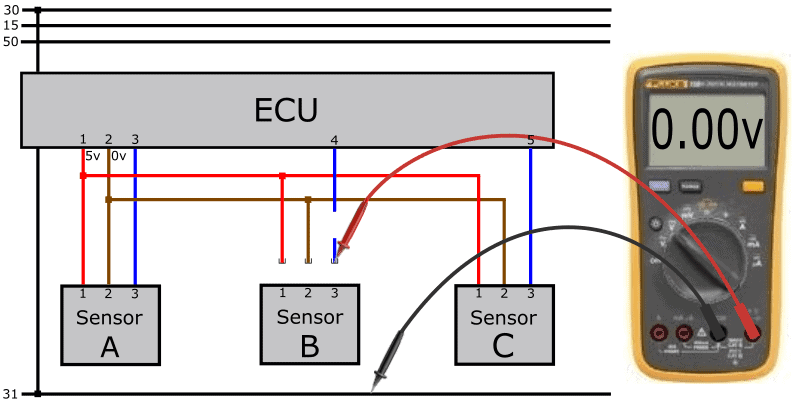
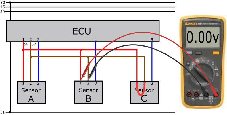
The following image shows the measurement of the supply voltage and ground of an active sensor.
The active sensor receives a positive supply (5 volts) and a ground from the control unit. In the measurement in the image next to this, the supply is therefore OK.
The signal that is sent via pin 3 of the sensor must be between 0.5 and 4.5 volts. To measure this, we place the red probe on pin 3 and we can leave the black probe on ground (pin 2).
In addition to active sensors, we also deal with passive and intelligent sensors. Read more about this on the page: sensor types and signals.
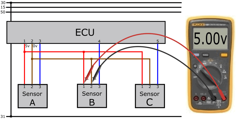
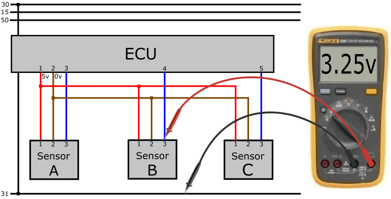
The sensor uses the 5 volt supply voltage to form the signal. The signal must be between 0.5 and 4.5 volts. The ECU reads the level of the voltage (or in other cases the frequency) and converts this into a value. This can be, for example, the value of the boost pressure sensor: at a turbo pressure of 1.5 bar the sensor sends a voltage of 3.25 volts to the ECU.
In this measurement the signal voltage is measured relative to ground and is OK.
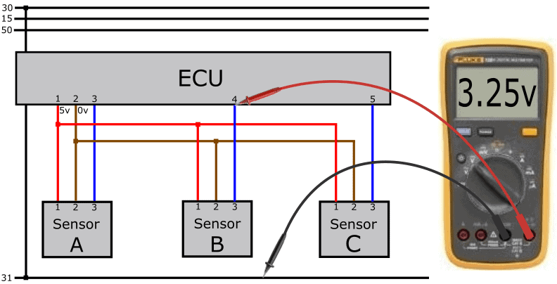
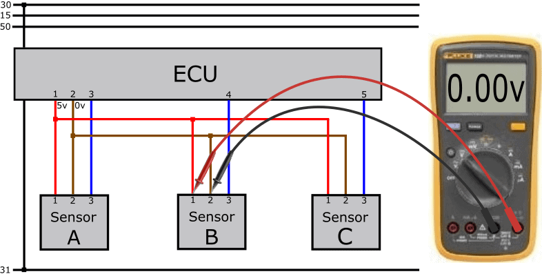
With the help of a breakout box we can measure in the ECU connector. This way we know which voltages the ECU outputs and receives.
In the next measurement we again measure 3.25 volts, but now at the ECU input. That means that the signal wire is intact: the voltage is passed on 1:1 from the sensor to the ECU.
The sensor signal will never be 0.0 or 5.0 volts. There is always a certain range. Often this is between 0.5 and 4.5 volts. The sensor will not output voltages lower than 0.5 or higher than 4.5 volts. In case of defects in the sensors or the wiring, the ECU can determine from the voltage level whether the value is within or outside the measuring range:
- voltages lower than 0.5 volts: the ECU generates a fault code with the description: “sensor X, short circuit to ground” or “short to ground”;
- for voltages higher than 4.5 volts, “short to positive” is indicated in the description of the fault code.
Active sensors can also transmit a digital signal. In many cases these sensors are not supplied by the ECU, but via terminal 15. In most cases we are dealing with a PWM signal.
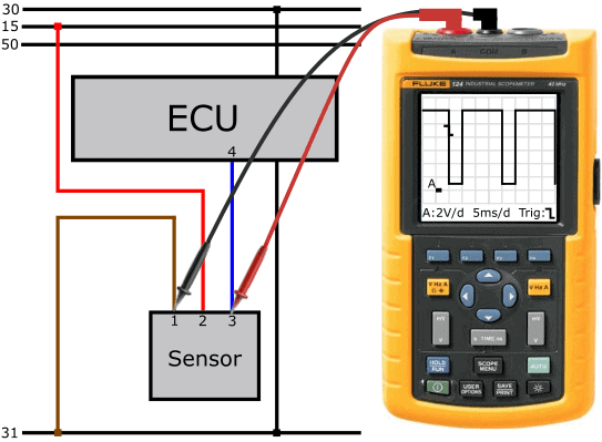
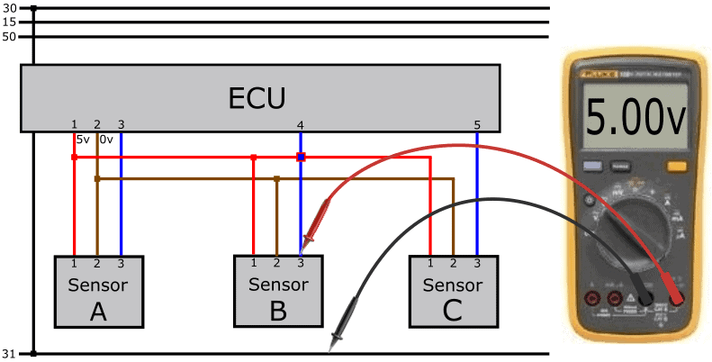
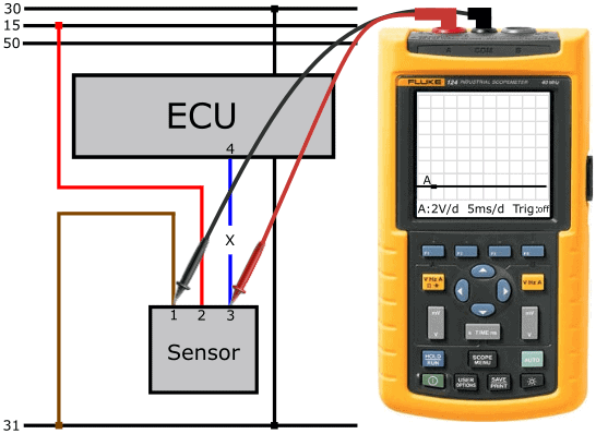
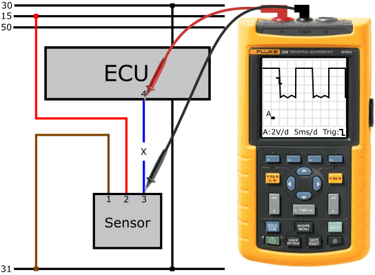
The following image shows part of the diagram where an active sensor has an external power supply and the signal wire is connected from pin 3 of the sensor to pin 4 of the ECU. With the oscilloscope, the voltage curve of the sensor is measured relative to the ground connection.
The scope is set to 2 volts and 5 milliseconds per division. The duty cycle is 50%.
In the paragraph: Fault 9 – Interrupted PWM signal wire we discuss the steps needed to make a proper diagnosis.
Diagnosing the sensor wiring:
Before we start diagnosing sensors, we must be familiar with the type of sensor (passive, active, intelligent) and the way in which the sensor sends its signal to the control unit (analog or digital, in the form of AM (Amplitude Modulation) or FM (Frequency Modulation)). After consulting the wiring diagram, we can estimate which voltages we are going to measure on the wiring.
In the following paragraphs, possible faults that can occur in practice are outlined. Instead of starting with “the customer’s complaint”, the cause is mentioned straight away; e.g. an interrupted wire, short circuit, etc. The aim is to gain insight into the measuring techniques. Because how do you proceed when there is a fault? And with which measurements do you find the cause?
Do you master the measuring techniques and are you curious about a case? Then visit the page: Case: fault fuel pressure sensor short circuit to positive.
Fault 1 – Interrupted signal wire:
With an interrupted signal wire, the signal voltage from the sensor cannot reach the ECU. In this paragraph you can read what you measure in this situation on the terminals of both the sensor and the ECU.
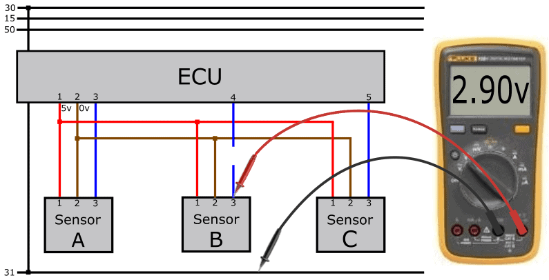
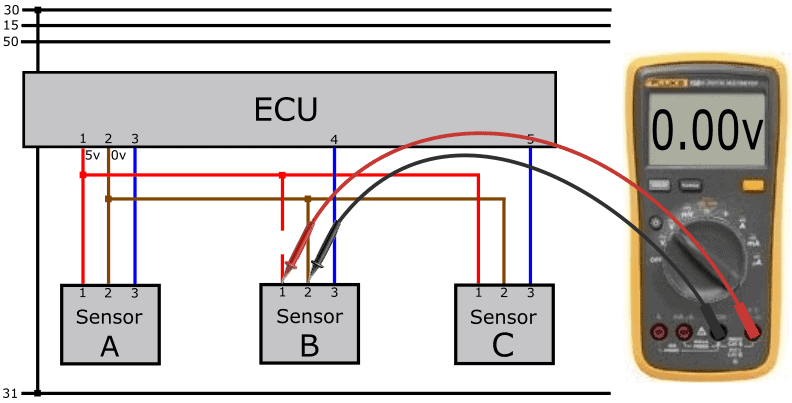
We carry out the following measurements on the active sensor and obtain the following readings:
- power wire (pin 1) relative to sensor ground (pin 2) is 5 volts;
- signal voltage relative to ground is 2.9 volts.
The supply and the generated sensor signal are OK. However, due to the interruption, the sensor signal does not reach the ECU.
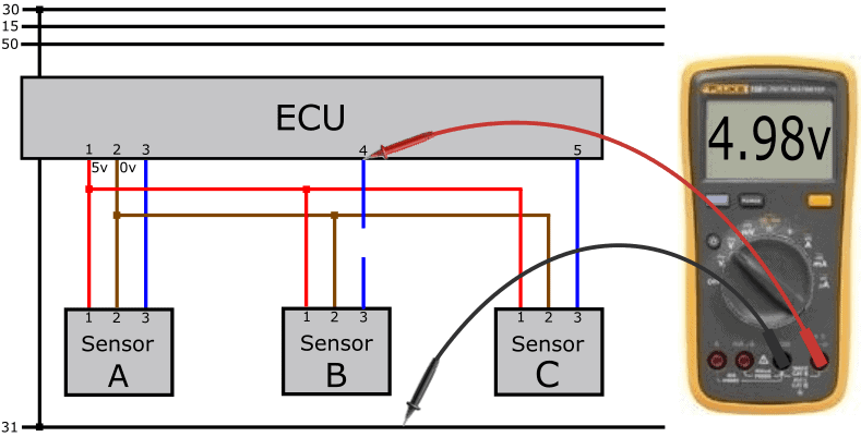
To measure the voltage at the ECU input, we use a breakout box.
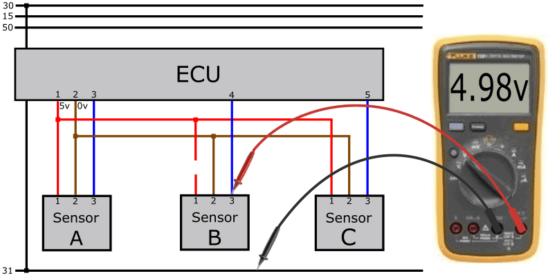
Using a breakout box, we perform a measurement on pin 4 of the ECU relative to ground (or pin 2 of the sensor). We measure a voltage of 4.98 volts.
The voltage on the ECU side is therefore higher than the voltage sent by the sensor. A circuit in the ECU is responsible for the output voltage of 4.98 volts. This is partly related to the way the signal is processed, but also to detecting interruptions.
The ECU now measures its own output voltage and recognises this, due to the supply voltage of 4.98 volts, as a short to positive.
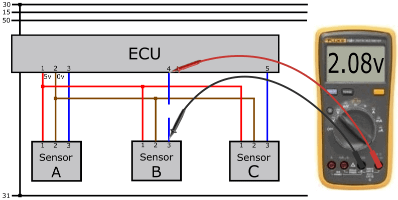
We then measure the voltage difference across the wire between the ECU and the sensor. In a fault-free situation, the voltage difference should be approximately 0 volts.
In this case we measure a voltage difference of 2.08 volts; namely 2.9 volts (sensor) compared with 4.98 volts (ECU).
The voltages can put you on the wrong track.
Remove the connector from the sensor. If there were no interruption in the wire, we would measure 4.98 volts from the ECU in the disconnected connector. Now we measure 4.98 volts on pin 4 of the ECU, but 0 volts in the disconnected connector.
In this case we can already conclude that the signal wire is interrupted.
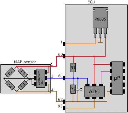
With an interrupted signal wire, the voltage on the signal input of the ECU is approximately 5.0 volts. On the page: sensor types and signals, in the paragraph: “power supply and signal processing” you can read how the ECU processes the signal from the active sensor. With that knowledge you can better understand how to deal with faults such as an interrupted signal wire.
The voltage of 4.98 volts is generated in the ECU. Between the power wire (coming from the 78L05) and the ADC there are several resistors which pull the signal voltage up to 5 volts when no voltage is coming in via the signal terminal. The ADC measures this voltage and converts it into a digital signal. So the ECU receives a signal with a voltage that is out of range and generates a fault code.
Note: with a similar fault, the voltage is not always exactly 4.98 or 5.0 volts!
On the page: Case: fault fuel pressure sensor – short circuit to positive a fault is described in which this voltage value deviates.
Fault 2 – Interrupted power wire:
Between the junction of the power wire between the three sensors and the connector of the sensor there is an interruption. The 5 volt supply voltage can no longer reach the sensor. Without supply voltage and ground, the sensor cannot function.
Because in the previous measurement we measured the supply and ground on the connector, we still have to rule out which of the two wires has a problem. We therefore measure the power on another sensor in the same power circuit. Measuring on the ECU is also possible, of course, if a breakout box is available.
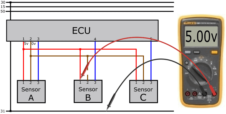
On pin 1 of sensor A relative to the ground of sensor B we measure 5 volts. This means that the ground of sensor B is OK.
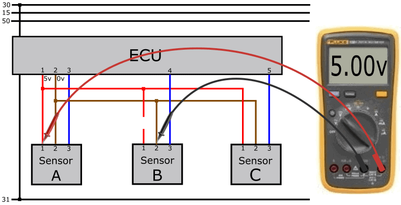
When, due to the interrupted power wire, no current flows through the electronics of the active sensor, we measure a voltage of 4.98 volts at the signal input of the ECU. We have a situation similar to that with the interrupted signal wire: the internal resistors in the ECU pull the signal voltage up to 4.98 volts. Because in this case the signal wire is intact, we also measure the voltage of 4.98 volts at the connector of the sensor.
In cases where the voltage is just above 5.0 volts, the voltage of the voltage stabiliser may have been lifted. See the paragraph: “power supply and signal processing” on the page: “sensor types and signals“.
Fault 3 – Interrupted ground wire:
In this case it is not the power, but the ground wire that is interrupted. A 5 volt supply does reach the sensor, but because we are measuring relative to an interrupted wire, the voltmeter has no reference voltage and shows 0 volts.

When moving the negative probe to the chassis or battery ground, the voltmeter does show 5 volts.
When we connect the negative probe to the ground terminal of sensors A and C, we should also measure a difference of 5 volts. If we were to measure 5 volts on pin 2 of sensor A but not 5 volts on sensor C, then the interruption is in the wire between sensor A and B, i.e. between the first two junctions.
Just as with the interrupted signal and power wire, we now also measure a voltage of 4.98 volts on the signal wire.
Fault 4 – Contact resistance:
In the previous paragraph we already discussed voltage loss as a result of contact resistance. In the following diagram we see a resistor in the power wire. When current flows through the power wire, the contact resistance causes an (assumed) too low voltage on pin 1 of connector B. We measure 4 volts instead of the 5 volts we expected to measure.
The stored DTC description in this case may be: “signal lower limit value undershot”.
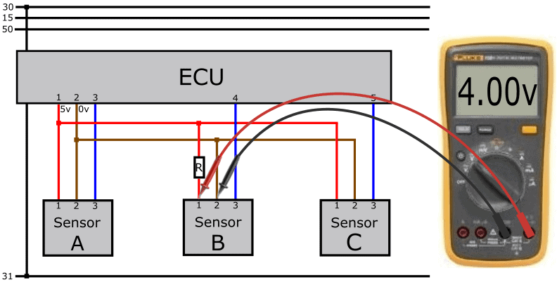
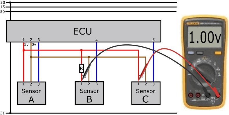
If we measure pin 1 of connector B relative to pin 1 of connector C, we should have a difference of (5-5) = 0 volts. We now see a difference of 1 volt.
Because the voltage loss is only present in the wire of sensor B and not of sensor C, we can assume that the wire between the junction of the horizontal wire in the diagram and the connector is not OK.
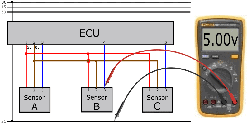
Fault 5 – Short circuit between power and signal wire:
A possible fault in the wiring is a short circuit. We encounter short circuits in the following situations:
- between the power wire and the signal wire (short to positive);
- between the ground wire and the signal wire (short to ground);
- between any of the three wires and / or to the bodywork (short to ground);
In this diagram we see a short circuit between the signal wire and the positive wire (short to positive). We measure a signal voltage that is equal to the 5‑volt supply voltage.
When measuring 5 volts on pin 3 of the sensor and pin 4 of the ECU, the problem may be internal to the sensor. To rule that out, we check the wiring for short circuits with an ohmmeter. To obtain a safe and correct measurement, we switch off the ECU, remove the ECU connector and also disconnect the connectors of the sensors that are interconnected by the junctions. Because there is a short circuit present, we measure a connection with the ohmmeter.
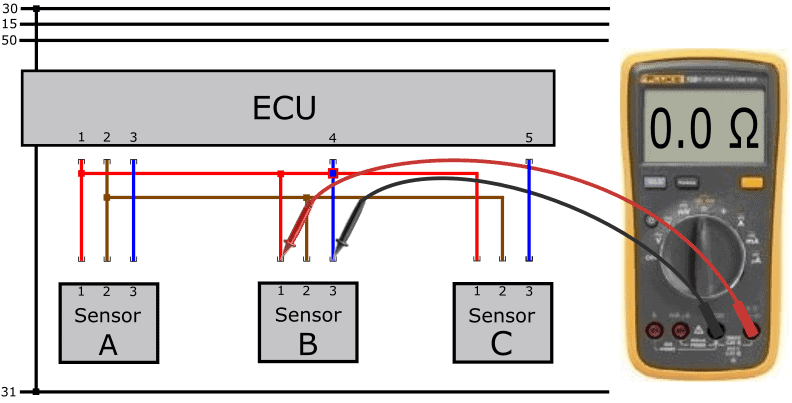
In this case it amounts to 0.0 Ohms because the wires are making contact with each other. In reality, this value may be a few Ohms higher. When there is no short circuit, the ohmmeter indicates OL or 1. (infinitely high resistance) because there is no electrical connection between the wires and test leads.
Fault 6 – Short circuit between power and ground wire:
In the event of a short circuit between the power and ground wires, the ECU switches off the power supply from pin 1. All sensors powered by pin 1 will stop functioning. Fault codes for multiple sensors will therefore be stored.
On the signal wire we also measure a voltage of 5.0 in this case, which originates from the ECU.
To rule out a short circuit, we disconnect, as in the previous paragraph, the connectors of both the ECU and all sensors in the relevant circuit. With an ohmmeter we measure the resistance between the red and brown wires.
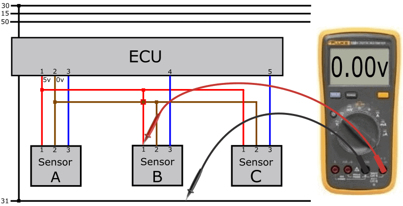
Fault 7 – Short circuit in sensor C:
When measuring the supply voltage relative to ground, we again measure 0 volts. In the previous fault there was a short circuit in the wiring. In this case, the short circuit is located internally in a sensor.
We disconnect the plugs of the sensors shown in the diagram one by one. When unplugging sensor C we no longer have a short circuit, and the ECU will again supply 5 volts to the positive wire. With some versions this happens automatically, with other types a key cycle is required.
Fault 8 – No supply voltage due to defective ECU:
In rare cases, the ECU can be the cause of the missing supply voltage. An internal circuit is damaged and no 5 volts is output.
The ECU is often wrongly condemned as defective. In most cases there is another cause. Therefore, first check for possible open circuits and short circuits in the wiring and the connected sensors. To rule out whether an internal defect in the ECU is the cause, we check all ground connections of the ECU.
In an extensive engine management system we see multiple circuits in one ECU, each with its own ground wire. We sometimes find as many as eight ground wires in a single connector. At the moment that one pin in the connector makes poor contact, or one ground wire in the wiring harness has an interruption, that circuit fails. Therefore measure, preferably under load with a test lamp (positive on the battery, negative on each ground terminal in the ECU connector) whether the ground is OK. The test lamp must light up equally bright at every ground wire. Does the lamp not light up at one ground terminal? Then you may have found the cause and the ECU is not defective.
Fault 9 – Interrupted PWM signal wire:
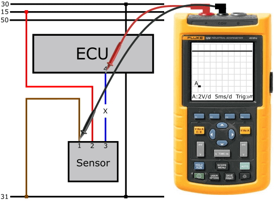
So far we have talked about analogue voltages that can be measured with a multimeter. In the case of a digital signal, a multimeter is no longer sufficient. We then use the oscilloscope. The following text refers to the oscilloscope in the images below. Here we see the Fluke 124 with a modified screen display.
The reason for carrying out this measurement is the fault description that can be derived from the fault code. The description reads: “sensor signal interrupted”.
In the scope image a constant voltage line of 0 volts can be seen. That means there is no voltage difference between the probes. If you have measured that the positive and ground wires of the sensor are OK (pin 2 relative to 1), in this case around 13 volts, there is something wrong with the signal wire. Note that the sensor can transmit the information in two ways:
- The sensor sends a positive voltage to the ECU (usually an analogue voltage);
- The ECU sends a voltage which is repeatedly switched to ground by the sensor on a time basis (by means of PWM; a digital signal).
In the example, the signal voltage on the sensor side is 0 volts, so we assume method 2.
Because the signal wire is interrupted, the sensor does not receive any voltage from the ECU.
We measure pin 4 of the ECU relative to pin 1 of the connector. The voltage is 12 volts. With these measurements we have established that the sensor input of the ECU is in order.
The ECU is apparently sending a constant voltage, but it is not reaching the sensor. The sensor therefore has no voltage to switch to ground.
With the next measurement we connect the probes to both sides of the signal wire. In this way we determine the voltage difference across the wire in active condition. In a fault-free situation, the voltage should be 0 volts. However, in the active part of the square wave we see a voltage of 12 volts. When we measure the full supply voltage in the maximum positive part of the square wave, in most cases we are dealing with an interrupted wire. That is also the case now: the output voltage of the ECU (pin 4 relative to ground) is 12 volts.
Furthermore, we see a deviation in the low part of the square wave: the voltage line drops to about 5 volts, remains constant for 10 milliseconds with a ripple, and then rises again to 12 volts. Because the oscilloscope is now in series between the pull‑up resistor in the ECU and the pull‑down resistor in the sensor, a series circuit is created. The scope has a high internal resistance, which affects the signal. For this reason, the signal is not usable.
Although the loaded voltage measurement is sufficient for a good diagnosis, it does no harm to use a resistance measurement to demonstrate that there really is a broken connection in the wire. In this case we measure an infinitely high resistance (OL or 1.).
After repairing the signal wire we again measure the signal voltage relative to ground. Note: we are measuring relative to ground here, so the “active” part of the sensor in the PWM signal is now inverted…
In this scope image we can see that:
- the voltage peaks at a maximum of 12 volts. Here the sensor is not active: the voltage on the signal wire is not being pulled to ground.
- the voltage drops to 1 volt. Here the sensor is active: the sensor connects the voltage from the ECU to ground via the sensor electronics.
The sensor contains an electronic circuit that still uses 1 volt. With this voltage, the ECU can also recognize that the sensor is switching on correctly. From the voltage levels, the ECU can determine whether the sensor is functioning properly:
- voltage over a longer period of time is equal to or higher than 12 volts:
ECU recognizes an interruption or short to positive; - voltage lower than 1 volt: ECU recognizes a short to ground.
Repairing an interrupted positive wire:
Of the five faults described in the previous paragraphs, most can be remedied fairly easily.
Cut the wire with the interruption or transition resistance off as close as possible in the wiring harness.
Apply insulation if necessary. Look for the nearest sensor that is connected in the same power circuit. For active sensors you can easily find this in a wiring diagram. In the diagram, the nearest sensor is C. Neatly solder a new wire to the positive wire.
Always use heat‑shrink tubing to prevent future problems caused by moisture ingress. If you seal it with electrical tape, new problems will arise within a foreseeable period of time!