Introduction:
Vehicles with electrified drivetrains (hybrid, fully EV, fuel cell) have the ability to brake electrically. When releasing the accelerator pedal, or with light braking, the electric motor works as a generator. The kinetic energy of the vehicle is converted into electrical energy for the HV battery. The range increases when the driver brakes gently often and the braking system gets the opportunity to brake regeneratively as much as possible. More about this can be read on the page: inverter.
As of 2026, electric braking is still always combined with the conventional hydraulic brake circuit. In case of an electrical fault, or in older vehicles during an emergency stop, the hydraulic brake circuit is (partially) activated. This serves as a backup. The following paragraphs show how manufacturers combine electric and hydraulic braking to ensure good comfort and safeguard safety in the event of a failure of the electrical system.
Drive by wire:
The “drive by wire” braking system aims to use electric assistance for hydraulic braking. There is no direct hydraulic connection between the brake pedal and the brake pistons in the calipers. By pressing the brake pedal, brake pressure is applied to a so‑called brake force simulator. The brake pressure is measured. An electric motor builds up the desired pressure in the hydraulic brake circuit. Compared to the conventional braking system, the drive by wire braking system offers the following advantages:
- No vacuum brake booster is required anymore, as the electric motor provides the required fluid pressure;
- Fluid leaks can be detected and isolated per brake. For that reason, a master cylinder for two separate brake circuits is no longer required;
- The driver does not notice the transition between electric and hydraulic braking at the moment the system switches from regenerative braking on the electric motors to braking by pressing the brake pads against the disc;
- Vibrations from the ABS system are no longer noticeable in the brake pedal;
- The (simulated) counterpressure in the brake pedal can be adjusted to the selected settings (comfort / sport).
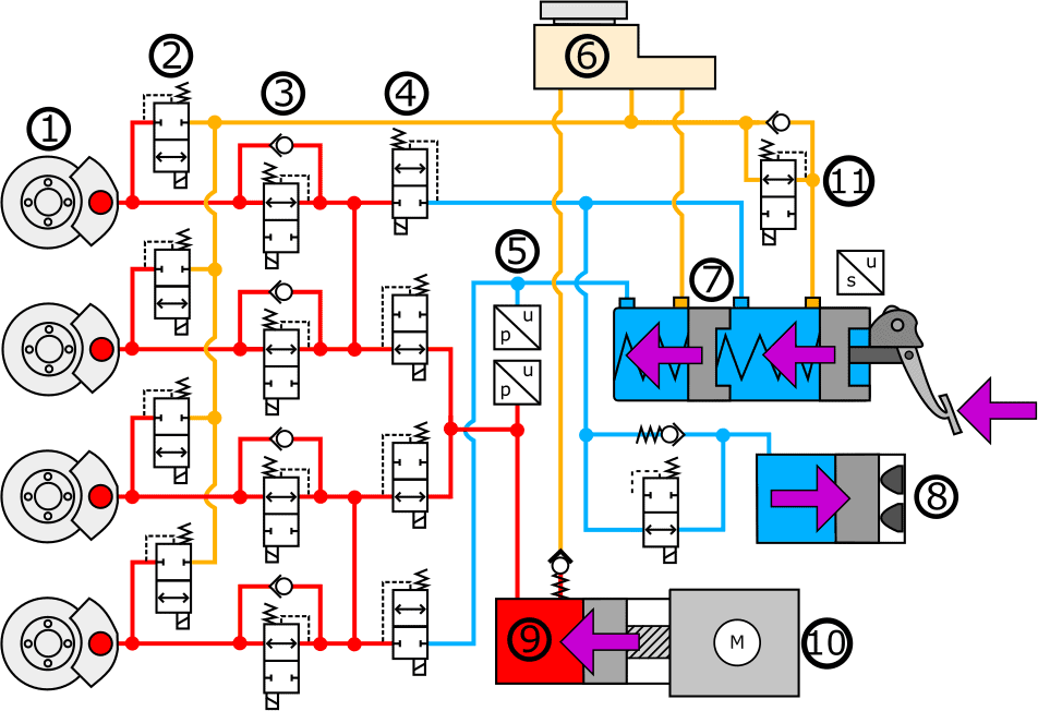
The hydraulic diagram below shows the system used by BMW (DSCi). Its operation is as follows:
When the driver operates the brake pedal, force is applied to the master cylinder (7). This master cylinder has two outlets: one to the brake pedal force simulator (8) and one to a decoupling valve. The simulation pressure is transmitted to the brake pedal force simulator via the blue line. In this component a counterpressure is created, which the driver recognizes as resistance in the brake cylinders. There is no physical connection from the master cylinder to the wheel brake cylinders. The simulation pressure is measured by a pressure sensor (5). Depending on the simulation pressure, the ECU controls the electric motor (10). This applies working pressure in the brake pressure cylinder (9). A pressure sensor on the working pressure side feeds the built‑up pressure back to the ECU. The red connections in the diagram show how the working pressure reaches the wheel brake cylinders (1) via the valves. The pressure‑holding valves (3) are open at rest, so the brake pressure from the brake pressure cylinder can be built up immediately. The pressure‑reducing valves (2) are closed at rest.
Legend:
- Brakes
- Pressure‑reducing valves
- Pressure‑holding valves
- Decoupling valves
- Pressure sensors for brake pressure working circuit and simulator circuit
- Brake fluid reservoir
- Master cylinder
- Brake pedal force simulator
- Brake pressure cylinder
- Electric motor
- Diagnostic valve
- Yellow connections: supply and return to brake fluid reservoir;
- Blue connections: simulation pressure;
- Red connections: working pressure (brake pressure).
If a leak is present near the brake pressure cylinder, or there is an electrical fault that prevents the electric motor from building up sufficient working pressure, then, to guarantee safety, the decoupling valves (4) are energized. The connection between the master cylinder and the wheel brake cylinders is opened and the connection to the brake pressure cylinder is closed. Because the brake booster is absent, the driver must press the brake pedal harder to brake.
Combination of electric and hydraulic braking:
Fully electric and hybrid vehicles always have a combination of an electric and a hydraulic braking system. The “brake by wire” braking system from the previous paragraph is not yet commonly used. In that system there is no direct connection between the brake pedal and the wheel brake cylinders. A powerful electric motor provides all braking force, even during an emergency stop. In that case, a brake booster is not needed.
In most electric and hybrid vehicles, a combination of electric and hydraulic braking is achieved as follows: under light (modulated) braking, regenerative (electric) braking takes place because the electric motors function as generators. Under heavy braking and/or in the event of faults, the hydraulic system immediately comes into play. A brake booster is used here to amplify the brake pressure. During deceleration, there is therefore an interaction between the electric motor and the mechanical brakes. This system is sometimes also called “drive by wire”, although this term is more suitable for the system described in the previous paragraph.
The diagram below is based on the Toyota Prius 3. By pressing the brake pedal (1), brake pressure is built up in the master cylinder (3). Under light braking, only the electric motors provide deceleration. The brake pressure simulator (4) provides counterpressure while the brake pedal is being depressed. The valve for the brake pressure simulator is opened during normal operation. Under heavy braking the lock valves (5) are opened and the valve for the simulator is closed. The front wheel calipers are supplied with brake pressure. Opening and closing the hydraulic valves (6) makes it possible for the brake pressure to also reach the rear wheels. The brake pressure sensors (from left to right: p lf to p rf) measure the pressure and transmit it to the ECU. By means of a PWM signal, the hydraulic valves (5, 6 and 7) are regulated according to the desired brake pressure.
The system is designed in such a way that, in the event of a power failure, the brake pressure on the rear wheels is completely relieved, and the pressure on the front wheels is controlled by the driver via the brake pedal.
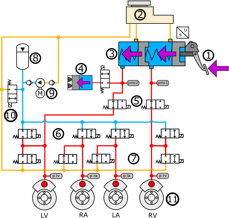
Legend:
- Brake pedal
- Brake fluid reservoir
- Tandem master cylinder
- Brake pressure simulator
- Lock valves
- Hydraulic valves (closed from left to right)
- Hydraulic valves, front closed, rear open
- Pressure accumulator
- Hydraulic pump driven by electric motor
- Pressure relief valve
- Yellow connections: supply and return to brake fluid reservoir;
- Blue connections: brake pressure supplied by hydraulic pump;
- Red connections: brake pressure supplied by master cylinder (with valves opened).
The hydraulic braking of the Toyota Prius 3 takes place via the front wheels. The rear wheels are not connected to the master cylinder. In modern vehicles, including the Kia Niro, this is the case: all four brake cylinders are actuated by the master cylinder via two circuits.
When braking vehicles with a similar braking system, under certain conditions a switchover takes place from electric to hydraulic braking. To ensure that the deceleration and pedal feel remain smooth, this braking system uses “brake blending”. This is described in the next paragraph.
Brake blending:
When releasing the accelerator pedal or braking in a controlled way, many electric vehicles use only the electric motors for deceleration. The kinetic energy is converted into electrical energy, increasing the vehicle’s range. The hydraulic braking system is hardly used. When a high level of deceleration is required, the electric brake and the hydraulic service brake work together. The interaction of the two braking systems is called “brake blending”. In earlier generations of hybrid and fully electric vehicles this was not smooth, and the rate of deceleration of the vehicle changed when the hydraulic brakes joined in. With current technologies, the driver no longer notices the transition between the two braking systems. Note: this is not the technique used with drive by wire.
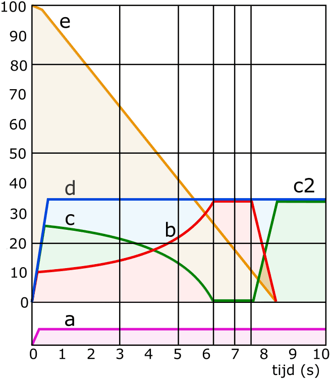
The graph shows the transition between the two braking systems while the deceleration remains constant. The pedal force applied by the driver (a) remains the same for 10 seconds. When braking begins, the hydraulic service brake and regenerative braking by the electric motors work together. During the first six seconds we see that deceleration due to regenerative braking increases. The electric motor functions as a generator and supplies the HV battery with the generated energy. The braking force of the hydraulic service brake decreases further and further until it no longer contributes. After approximately 7.5 seconds, the vehicle nears standstill and the electric braking force drops away. The hydraulic braking force increases again. After 8.5 seconds the vehicle is stationary. The driver keeps the brake pedal pressed for a short while.
a: pedal force from the driver
b: deceleration by regenerative braking (using the electric motor)
c: deceleration by hydraulic service brake
d: deceleration desired by the driver
e: speed reduction
d = c + b
Related pages: