Topics:
- Introduction
- Multiple networks in a car
- CAN network with the control units
- CAN bus signals
- Speeds and voltage levels
- Structure of the CAN bus message of a (standard) 11-bit identifier
- Structure of the CAN bus message of an (extended) 28-bit identifier
- Math channel and serial decoding
- Error detection by means of Bitstuffing and CRC & ACK delimiters
- Twisted Pair wiring
- Termination resistors
- Gateway
- CAN bus diagnostics
Introduction:
Modern vehicles are full of electronics. The control units collect and process data from sensors and control actuators. Different ECUs often use the same data: the accelerator pedal position sensor registers the position of the accelerator pedal. This signal is transmitted directly to the engine ECU via the wiring. The engine ECU is not the only ECU that uses this signal:
- The engine ECU uses the signal from the accelerator pedal position sensor to control the throttle valve, to provide acceleration enrichment by keeping the injectors open longer when accelerating, to adjust the ignition timing and possibly to control the wastegate or VGT adjustment of the turbo;
- The automatic transmission ECU uses the accelerator pedal position to determine the shift times of the clutches in the automatic gearbox. If the accelerator pedal is pressed down only slightly, the automatic gearbox will shift up at a lower engine speed than when the accelerator pedal is pressed halfway down. Rapidly flooring the accelerator pedal will activate the “kick down” by shifting to a lower gear and allowing the engine to rev higher;
- The level of throttle input in a bend can be a reason for the ESP ECU to intervene by reducing engine power and, if necessary, applying the brake of a spinning wheel.
During an ESP intervention, engine power is reduced by (partially) closing the throttle valve and injecting less fuel. In addition, a warning light in the instrument cluster will light up or flash to alert the driver that the ESP is active.
The above already clearly shows the cooperation between different ECUs. CAN bus ensures that ECUs communicate with each other and can therefore exchange data with each other. CAN is an abbreviation for: Controller Area Network.
In the 1980s, cars were increasingly equipped with accessories and manufacturers started to build in control units. Every function received a separate wire. As a result, the wire gauge and the number of connector connections increased significantly.
Thick wiring looms have the disadvantage that routing them behind interior trim is difficult and the likelihood of malfunctions increases considerably.
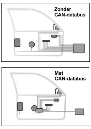
With CAN bus, ECUs communicate using just two wires: CAN high and CAN low. All communication between the ECUs takes place via these two wires. In the following two images it is clearly visible that the number of wires in a single door already decreases considerably when using CAN bus.
Dozens of control units can be connected to the two CAN bus wires. All connected control units can exchange data with each other.
The image below shows a vehicle with eleven control units (indicated by the red blocks). These control units are all connected to each other with two wires; an orange and a green wire. These wires represent CAN high and CAN low. Each control unit has its own function and can communicate with any other control unit in the network by means of the CAN bus. More detailed information about the control units can be found on the control units page.
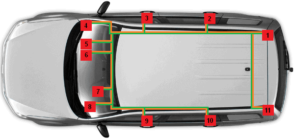
1. Control unit for tow bar installation
2. Right rear door control unit
3. Right front door control unit
4. Gateway
5. Comfort control unit
6. Control unit for alarm system
7. Instrument cluster
8. Steering column electronics control unit
9. Left front door control unit
10. Left rear door control unit
11. Park Distance Control unit
With the advent of the CAN bus, EOBD has also been expanded. EOBD stands for European On Board Diagnosis. EOBD relates to emissions. Various sensors from the engine and exhaust pass information on to the ECU. If there are incorrect values (because, for example, there is poor combustion), an MIL (Motor Indication Light) will illuminate. That is a sign that the car needs to be read out. A diagnostic tester must then be connected to the OBD connector to read the faults. Based on the fault, the ECU has stored a hexadecimal fault code, which is displayed by the diagnostic tester as a P-code or a fault with text (the latter is more brand-specific). Click here for more information about OBD1, OBD II and EOBD.
Multiple networks in a car:
There can be multiple networks in a car. The image below shows an overview with legend of control units in multiple networks of a BMW 3-series E90.
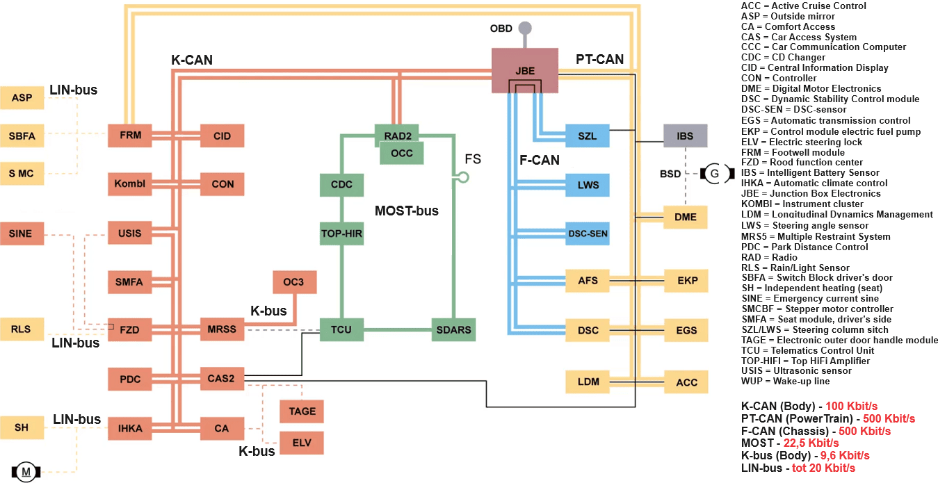
The K-CAN, PT-CAN and F-CAN networks in the image above fall under CAN bus. The differences are the speeds with their associated voltage levels and applications. The PowerTrain CAN and the F-CAN do have the same high-speed rate and voltage levels, but the difference is that PT-CAN is used for engine and transmission control, while F-CAN contains the control units of the chassis.
CAN network with the control units
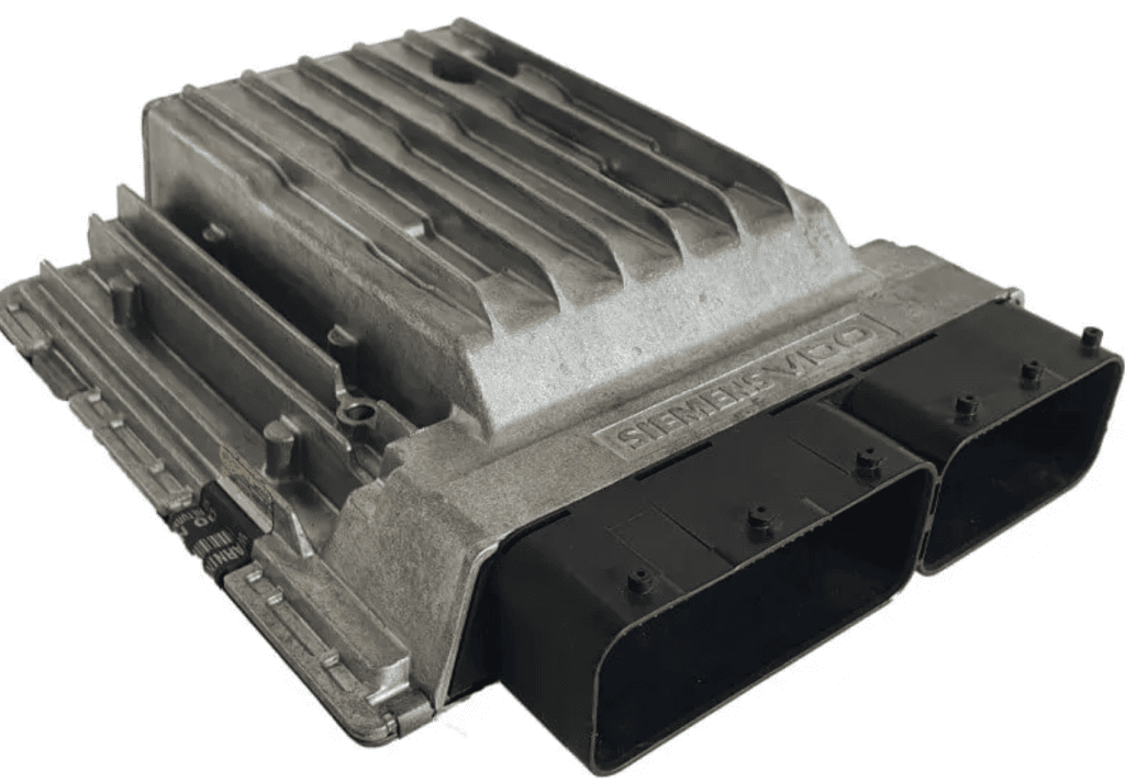
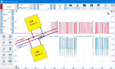
The CAN bus network consists of control units that are equipped with hardware and software to receive, process and transmit messages. For data transfer a CAN high wire and a CAN low wire are used. In the image below, CAN high is colored red and CAN low is colored blue.
The control units (also called control modules or nodes) are connected to these wires. All control units can both send and receive information. An example of a network is the CAN bus system in the interior of the car; various control units can be connected to one bus system here.
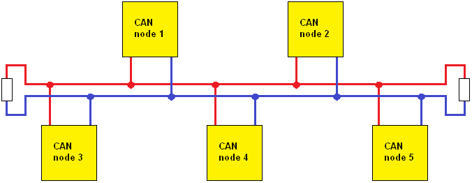
As an example, we take a reversing camera (node 5) that is retrofitted. This camera is mounted at the license plate holder or handle. The CAN wiring is connected at any point in the interior. The condition is that the node of the camera contains the correct identifier (pre-programmed by the manufacturer), because the other control units need to recognize it. Once the camera is registered on the supported radio, the image is immediately visible.
After programming the software, the radio receives a signal from the gearbox that reverse gear has been selected. At that moment, the radio switches to the image from the reversing camera. When first gear (forward) is selected, the image switches off again. All this is thanks to the data transfer of the CAN bus system.
Unsupported equipment (with, for example, an incorrect identifier) can cause problems. If it sends messages that are not recognized by other control units, a fault message will be generated. This type of equipment can also cause the CAN bus to remain active after switching off the ignition. The car will then not go into “sleep mode”, causing the battery to discharge quickly. In that case we speak of a clandestine consumer.
CAN bus signals:
The CAN bus system uses the broadcast principle; a transmitter puts a message on the CAN bus. Every node on the same bus receives the message. However, the transmitter indicates in the message for which nodes the message is intended. All nodes receive the message and then give their feedback (more on this later). The nodes for which the message is not intended recognize this and ignore it.
A CAN bus signal consists of a CAN high and CAN low voltage. In the image below, CAN high is shown in red and CAN low in blue. The high and low signals are identical, but mirrored. When the bus becomes dominant, the voltage of CAN high rises from 2.5 to 3.5 volts and CAN low drops from 2.5 to 1.5 volts. In recessive condition (at rest) both voltages are 2.5 volts.
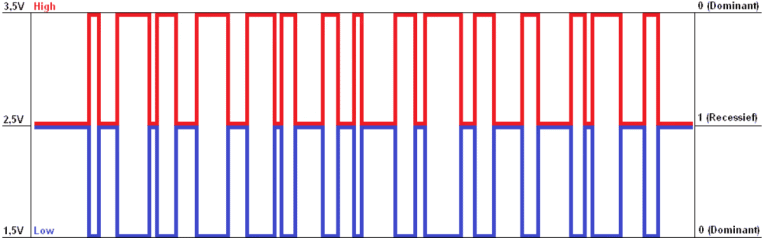
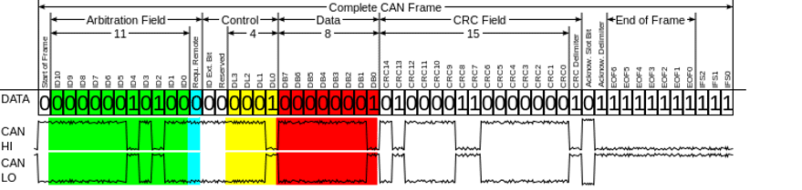
The image above shows an example of a measurement with an oscilloscope. It is clearly visible that both voltages are identical to each other, only mirrored. Ultimately, the voltage difference in the active (dominant) area is 2 volts. This refers to the difference between 1.5 and 3.5 volts. The difference of 2 volts is seen as a 0 (dominant) and the difference of 0 volts as a 1 (recessive).
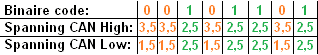
If a (transmitting) node wants to send the binary code “0 0 1 0 1 1 0 1”, it will apply the above-mentioned voltages to CAN high and CAN low (see the example above). The receiving node will see these voltages again as a binary code, and then convert them into a hexadecimal code. The binary code mentioned will be converted from binary to 2D in hexadecimal.
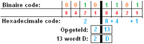
To convert binary to hexadecimal, it is helpful to draw a table of 8 boxes with a thick line in the middle. Name the boxes on the right 1, 2, 4 and 8 (see the red numbers in the image). Then do the same on the left. Write down the numbers above which there is a 1 from the binary code. On the left that is only 2, on the right that is 8, 4 and 1. Add up everything on the right (13) and do the same on the left (2). Hexadecimal continues from 10 as A, 11 = B, 12 = C, 13 = D. So that ultimately makes 2D.
More information about converting binary to (hexa-)decimal and vice versa can be found on the page Binary, Decimal and Hexadecimal. Here you will find clear examples described in detail.
Speeds and voltage levels:
In vehicles we can encounter CAN bus networks with different speeds:
- High speed: ECUs involved with the drivetrain, including engine electronics, transmission, ABS/ESP, EBS (commercial vehicles);
- Medium or low speed: interior electronics such as the instrument cluster, radio, climate control, parking brake, tow bar.
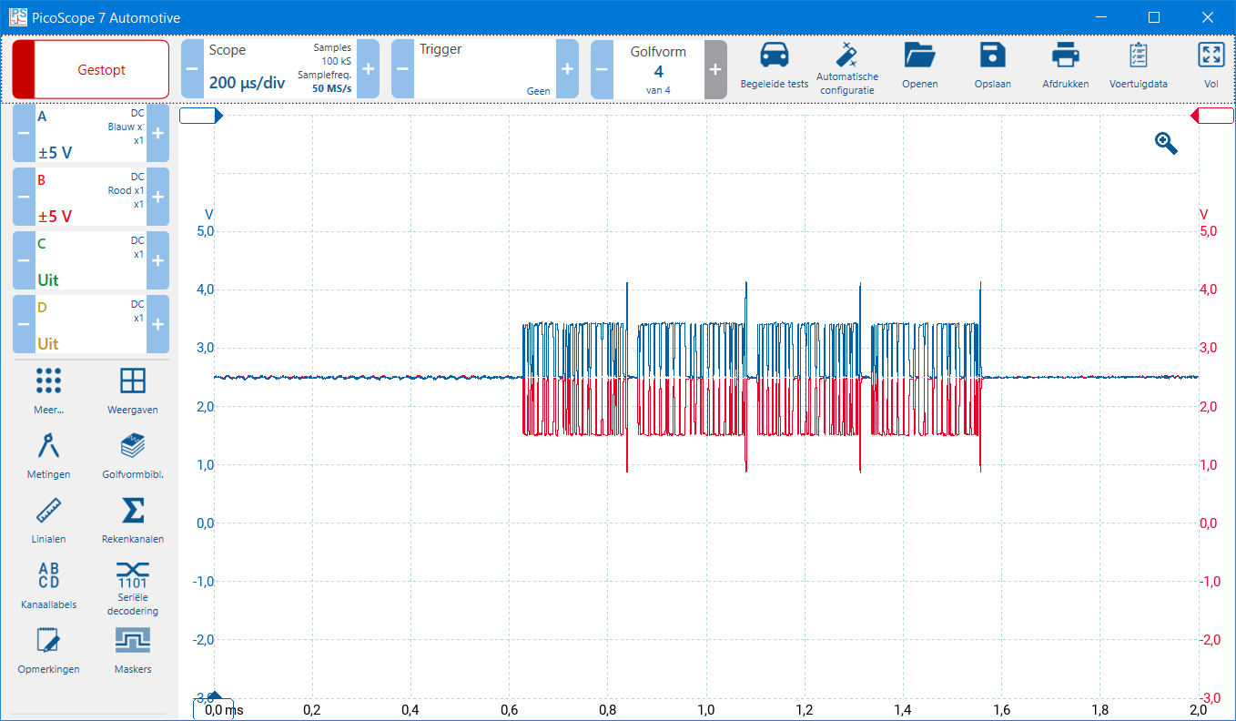
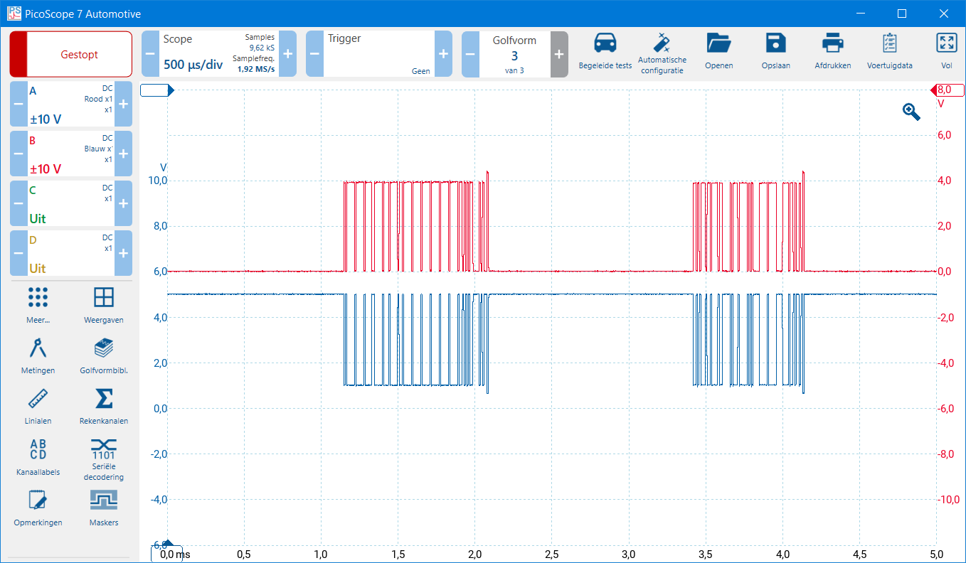
In the two images below, the CAN high and CAN low signals of the high-speed CAN bus can be seen. At rest, the voltage of both signals is 2.5 volts. To send a message, CAN high rises from 2.5 to 3.5 volts and CAN low drops from 2.5 to 1.5 volts.
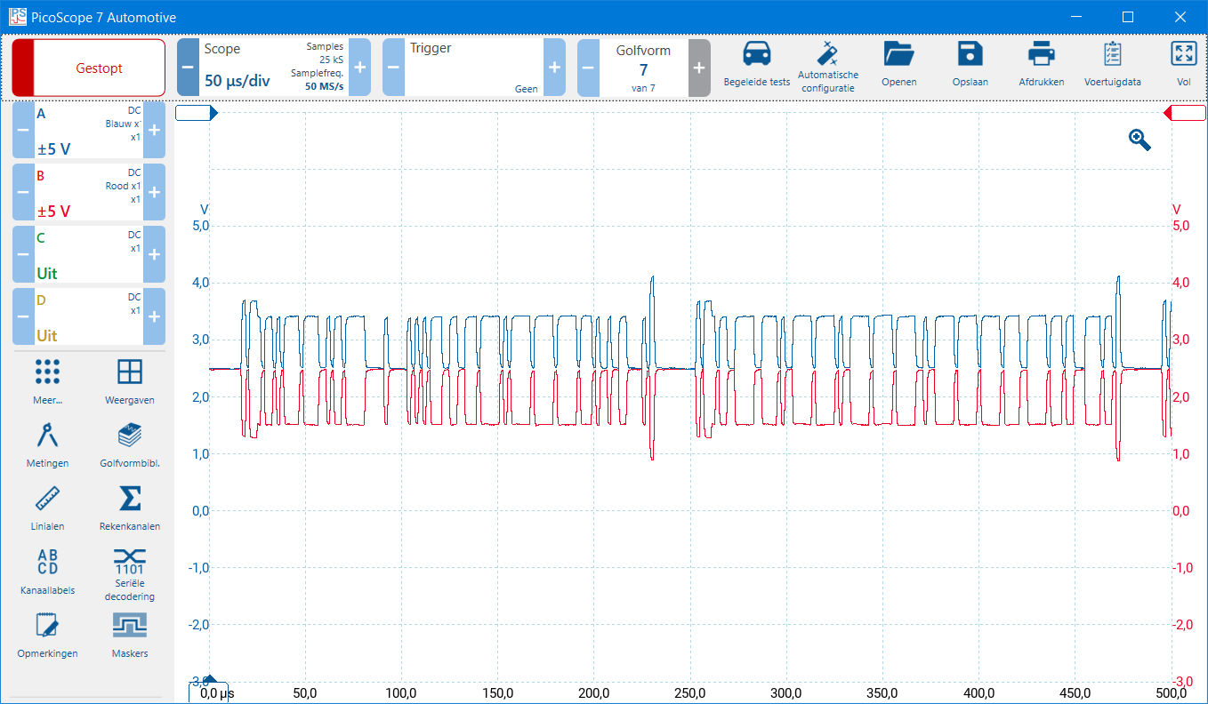
Below, the high-speed CAN signal is shown once again, but now zoomed in (50 microseconds per division), whereas in the signal above the scope was set to 200 microseconds per division.
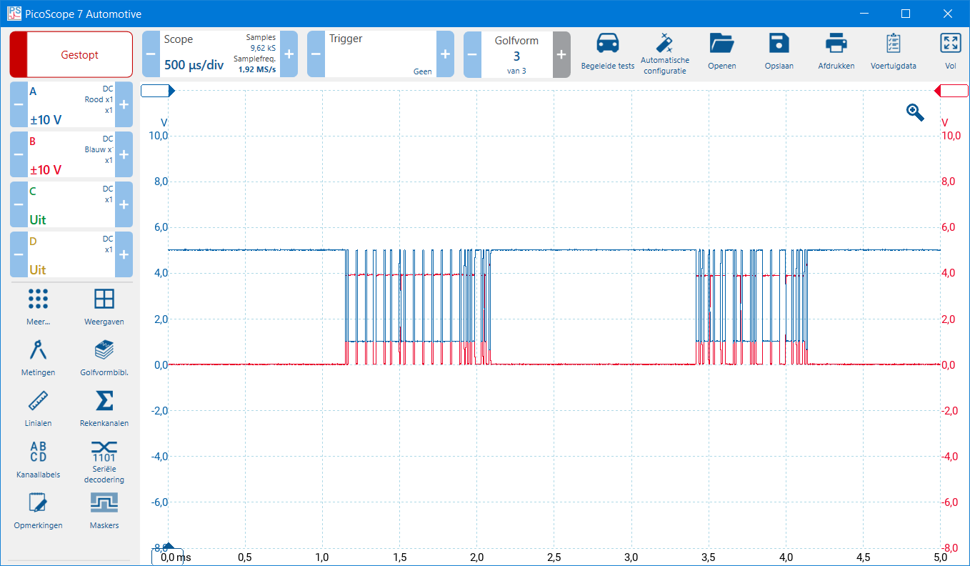
In comfort electronics, the high speed of communication is less important and is therefore implemented at a lower speed. Characteristic of the medium or low speed CAN bus are the voltage levels at rest and when forming a message as follows:
- CAN-high is 0 volts at rest (recessive) and rises to 4 volts (dominant) to transmit a bit;
- CAN-low is 5 volts at rest (recessive) and drops to 1 volt to transmit a bit.
In the measurement where the zero lines of channels A and B are set at the same height, you can see that the voltages are “slid into” each other. That makes it difficult to read the integrity of the CAN-high and CAN-low signals. The image below shows the oscilloscope display with the high and low:
- CAN-high (red) rises from 0 to 4 volts
- CAN-low (blue) drops from 5 to 1 volt.
To be able to assess the integrity of the messages, it is advisable to shift the zero lines. In the image below, the zero line of channel A has been moved downwards and that of channel B upwards. This pulls the displayed signals apart and makes the course of the voltages easier to see.
Structure of the CAN bus message with a (standard) 11-bit identifier:
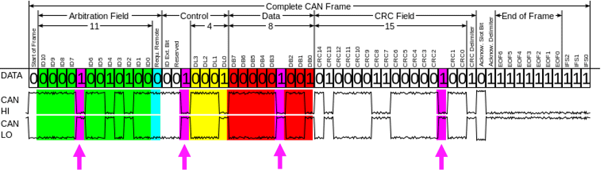
The structure of a CAN bus message is always based on the image below. There are differences in the structure; for example, the ARB and CTRL fields of an 11-bit identifier and a 29-bit identifier are different. The information below relates to the 11-bit identifier. For your information: a 29-bit identifier has room for more data than the 11-bit one. More about this later.
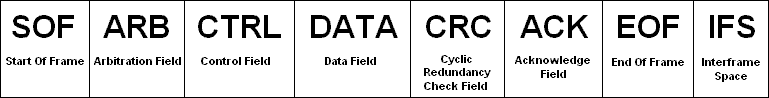
The structure of the message is now briefly summarized and described in more detail later on:
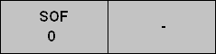
SOF:
Every CAN message starts with an SOF (Start Of Frame). When a node wants to transmit a message, it will place a dominant bit on the bus. The CAN bus is always recessive at rest (a 1, so both CAN-High and CAN-Low are 2 Volts). The dominant bit (a 0) indicates that other nodes must wait to transmit a message until the entire message has been placed. Only after the IFS (Interframe Space) may the next node start transmitting its message. Even if it is an important message, it cannot cut in.
When 2 nodes want to transmit a message at the same time (which they are unaware of) and thus together make the bus dominant by placing a 0, the ARB (arbitration) determines which message goes first.
From this point on, for each part of the CAN bus message that is discussed, that section will be added to this grey image. In this way I try to keep an overview. The message has started with the SOF.
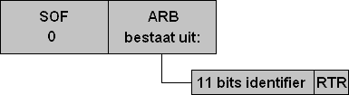
ARB:
The arbitration field of an 11-bit identifier consists of two parts: the identifier and the RTR bit.
Suppose two nodes make the CAN bus dominant at the same time. The node with the less important message then waits until the more important message has been fully placed (until after the IFS). In the identifier of the message there is a sequence of ones and zeros. These values are deliberately assigned to a message by the programmer. An identifier that contains a 0 in the message (dominant) has a higher priority than an identifier that contains a 1 in the message (recessive).
The bit value 0 (dominant) always overrules a bit value 1 (recessive). If two nodes transmit at the same time and one sends a 0 and the other a 1, the resulting bus level will be 0. The node that sent the 1 notices this difference, stops transmitting, and becomes a receiver. This creates the priority on the bus.
The animation below with three ECUs shows how the messages containing a 1 drop out and how the message with the most zeros from the rightmost control unit is ultimately allowed to be transmitted.
The three ECUs start in the identifier by placing an 11-bit message. At the SOF, the dominant bit is placed. Then, the first two bits of the three identifiers are the same (0 0). The third bit is a 1 in the second ECU and a 0 in the third ECU. Dominant prevails, so ECU 3 places the CAN message. The two ECUs whose bits were recessive then listen to the complete message and determine whether they need to do something with it.
The grey image of the SOF below is now extended with the ARB, which consists of two parts: the identifier and the RTR bit.
RTR bit:
The last bit of the 11-bit identifier is the Remote Transmit Request bit (RTR bit). This bit determines whether a CAN frame contains data or whether it is requesting data.
0 = data frame (dominant): the message contains data in the data field
1 = remote frame (recessive): the message requests data from another ECU, which will then send a data frame with the same identifier
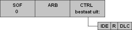
CTRL:
The Control Field consists of the IDE (Identifier Extension), an R bit and the DLC. The IDE bit indicates whether it is a standard (11-bit) or an extended (29-bit) identifier.
0 = standard identifier (11 bits)
1 = extended identifier (29 bits)
The R bit is reserved for future use and is always recessive in standard frames.
Next comes the DLC. A CAN network can transmit a maximum of 8 data bytes. One byte contains 8 bits, so in total a maximum of 64 bits of data can be transmitted according to the standard protocol. The Control Field specifies how much data is being transmitted. It is not meaningful to send a large message with empty data fields for a simple confirmation (for example 1 for on or 0 for off). The DLC (Data Length Code) therefore indicates how many bytes of data are being sent. The DLC is a function in the programming software and is assigned beforehand by the programmer.
If the DLC specifies one byte, then 8 bits of data are transmitted. For short confirmation messages this is sufficient. For extensive messages, the DLC will contain a value of up to 8 data bytes.
The example has been expanded again. The IDE, R and DLC have been added.
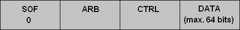
DATA:
The actual data to be transmitted is placed in the data field. The size depends on the value of the DLC (Data Length Code). As mentioned earlier, the DLC has a maximum of 8 bytes. Each byte consists of 8 bits, so the data field can contain up to 64 bits in total.
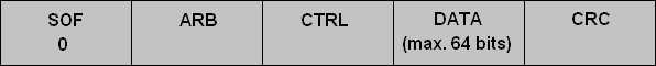
CRC:
The Cyclic Redundancy Check consists of a mathematical calculation that is sent along with the CAN message. The transmitting node calculates a check value over the message up to that point: SOF, ARB, CTRL and DATA. This calculation forms the CRC.
When the receiving node has received the message including the CRC, it performs the same calculation over the received part of the message (up to and including the DATA field) and compares the result with the transmitted CRC value. If the values do not match (for example due to an incorrect bit or interference), the message is not accepted and a request is made to retransmit it, with a maximum number of retry attempts.
The example has been expanded with the CRC field.
ACK:
The Acknowledge Field is used for the receipt confirmation. When the transmitter has sent the message up to and including the CRC, the ACK slot follows. The transmitter places a recessive bit (1) on the bus in this slot. If one or more receiving nodes have correctly received the message, they will overwrite this recessive bit with a dominant bit (0). It does not matter how many nodes give the confirmation: one dominant confirmation is sufficient.
This is followed by the ACK delimiter, which is always recessive. The transmission of the message is then continued.

EOF:
The End Of Frame consists of 7 recessive bits (1 1 1 1 1 1 1). For all control units this is a sign that the message has ended.

IFS:
To prevent interference, an Inter Frame Space is always applied after the EOF. The IFS consists of 11 recessive bits. All nodes wait until these 11 recessive bits have passed before they start transmitting a message. After these 11 recessive bits, for example, 2 nodes can again start transmitting a message at the same time. The ARB (Arbitration) is then consulted again to determine which message has the highest priority. The entire cycle then starts again.
Structure of the CAN bus message with an (extended) 29-bit identifier:
The 11-bit identifier was designed in a period when vehicles still contained relatively few control units (nodes). It soon became clear that there was a need for more identifier capacity. An 11-bit identifier offers 2^11 = 2048 possibilities, of which 2032 unique combinations are available for messages. Modern vehicles therefore use the extended 29-bit identifier, called the extended identifier. This allows 2^29 = 536870912 combinations. This provides more than enough capacity, also for future applications.
Several things change in a CAN bus message when an extended identifier is used. Both types of identifiers (standard and extended) can exist side by side. The message therefore indicates which type of identifier is used, after which the rest of the message structure follows.
The basis of the 11-bit identifier remains and forms the starting point. Below, only the parts that differ when a 29-bit identifier is used are described. The SOF (Start Of Frame) remains unchanged: the transmitting node places a dominant bit when the message is started. After that, the ARB and CTRL fields follow, where the differences become visible.
ARB:
During arbitration, the standard 11-bit identifier (the first part of the 29-bit identifier) is first placed. The RTR bit (which is in this position in the 11-bit identifier) is moved to the end of the ARB field in the extended identifier. In the original position of the RTR bit, the SRR bit (Substitute Remote Request) is now placed. This SRR bit is always recessive (1) in an extended identifier.
After the SRR bit comes the IDE bit. In a standard 11-bit message this bit is located in the CTRL field. In an extended identifier, the IDE bit is removed from the control field and placed directly after the SRR bit in the arbitration field.
For clarification, the images below show the standard identifier (11 bits) and the extended identifier (29 bits).
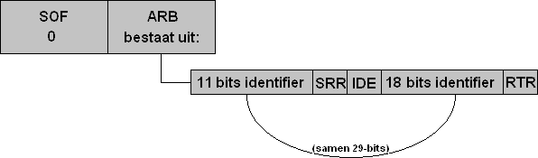
The IDE bit stands for Identifier Extension. From the IDE bit it can be seen whether it is a standard or extended identifier.
IDE 0 = Standard (11-bit ID)
IDE 1 = Extended (29-bit ID)
After the IDE bit comes the rest of the extended identifier. The 11 and 18 bits together make 29. These cannot be placed in the message as a single whole, because then the CAN protocol would no longer be correct. In principle, the IDE bit now indicates that the message is split into two parts.
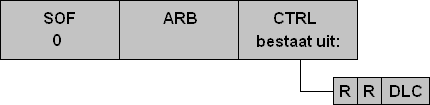
CTRL:
With the extended identifier, the Control Field has been modified. The IDE bit has been moved to the ARB.
The IDE bit is replaced by an R bit (reserve). This is recessive by default. This is followed by another R bit and the DLC (Data Length Code), which indicates how many bytes the message will contain.
Again, the control fields of both the 11‑bit and the 29‑bit identifiers are shown.
Math channel and serial decoding:
When measuring CAN bus, the following functions can help in analysing the signals: the math channel and serial decoding. Below you will find the explanation of the math channel. Under the PicoScope screenshot you will find the explanation of serial decoding.
Math channel:
The math channel makes a mathematical comparison between two measurement channels. When CAN Low is measured on channel A and CAN High on channel B, we select “B-A”. An extra Y-axis with a voltage scale appears on the screen. Below the voltage traces of channels A and B we then see a voltage from 0 to 2 volts:
- Recessive: B-A = 2.5 – 2.5 = 0 volt
- Dominant: B-A = 3.5 – 1.5 = 2 volt
The math channel helps in analysing the signal behaviour, even if the measured voltages show some noise. You can find more information about this in the Twisted Pair paragraph.
Under the screenshot you will find the explanation of serial decoding.
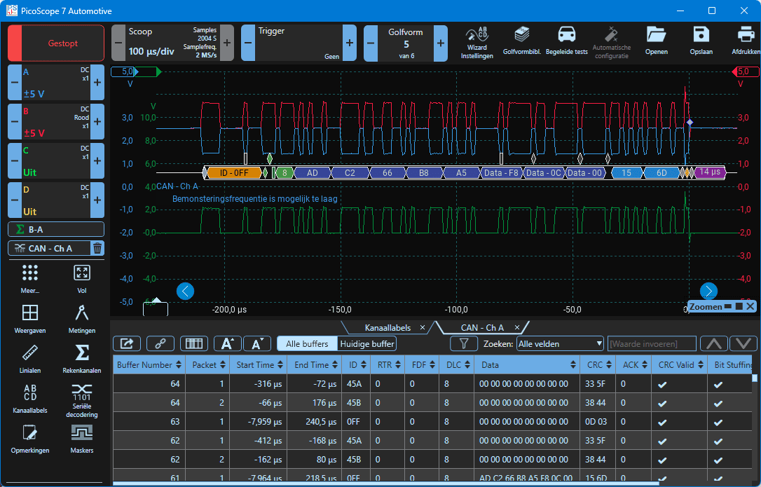
Serial decoding:
In the left column of the PicoScope software you will find the “Serial decoding” button. After selecting this function, a window with options appears in which the desired measurement channel must be selected (channel A is chosen in this example), and the settings for the baud rate and high or low are shown. The baud rate equals the CAN speed and is usually already set correctly automatically. Under “High or Low” we choose whether we are going to measure a CAN High or CAN Low. Because channel A is selected and this is CAN Low, we choose “Low”. In the next window, settings for the display (decimal, hexadecimal) can be changed if desired, but they can be left as they are.
After confirming, an extra coloured bar appears below the voltage trace, with the read-out data and the hexadecimal data at the bottom of the screen. The coloured blocks show the structure of the CAN message. In the scope image, the colours are shown without red messages with crosses, and in the lower data field all texts are blue with a V for valid. This means that the CAN data can be read correctly by the PicoScope software. In most cases we can therefore assume that the ECUs in the car can also read this data. As soon as the data contains errors, we see this reflected in the serial decoding by red texts and crosses.
Error detection by means of Bitstuffing and CRC & ACK delimiters:
Bitstuffing:
To maintain synchronisation between transmitting and receiving nodes, bit stuffing is applied. This means that after five identical bits an opposite bit is automatically added by the transmitter. This does not change the content of the original data, but an extra bit is inserted.
The receiver recognises bit stuffing. As soon as five consecutive identical bits have been received, the next (opposite) bit will be removed. As a result, the original bit pattern is preserved.
When a message consists for example of only ones, the transmitter will insert a zero after every sequence of five ones. The message length therefore increases, but these extra bits do not count towards the DLC (Data Length Code). The receiver removes the inserted bits again and thus retains the original bit pattern.
CRC & ACK delimiters:
CRC and ACK delimiters are fixed recessive bits that follow directly after the CRC and ACK fields, respectively. These bits have a fixed value, so both transmitter and receivers know exactly which bus state must be present here. If a node detects a deviating value, this is interpreted as a bit error. The node then marks the message as invalid and generates an error frame. The message will be retransmitted later, depending on the error handling mechanism and the configured protocol layer.
Suppose a CAN message contains the following (fictitious) data field: 1010
The transmitter must now determine a simple check value (CRC). In this example we use a simple calculation instead of the real polynomial division, to make the principle easy to understand:
Add the digits together:
1 + 0 + 1 + 0 = 2Convert the result to a binary value:
2 decimal = 10 binaryThis binary value is sent along as CRC after the message:
1010 10
The receiver does the same:
1 + 0 + 1 + 0 = 2 → 10 binary
The received CRC was also 10 → so the message is correct.
If a bit is received incorrectly due to noise (for example 1010 becomes 1110):
1 + 1 + 1 + 0 = 3 → 11 binary
The calculated value (11) then does not match the received CRC (10). The receiver now knows that there is an error in the message.
This example shows the basic principle:
The CRC is a check value that the receiver uses to confirm that all bits have remained the same during transmission. In reality, the calculation is much more extensive and accurate, so that multiple bit errors at the same time can also be detected.
Twisted pair wiring:
Twisted pair wiring is used as cabling for the CAN bus. The CAN High and CAN Low wires are twisted (braided) around each other, as shown in the image. Because both wires continually change position due to these twists, they receive almost the same interference signals from outside. As a result, the voltage difference between CAN High and CAN Low remains stable. This form of noise suppression is called common-mode noise rejection and is an important advantage of twisted pair wiring.
In addition, the CAN bus operates differentially. This means that it is not the absolute voltage on a single wire that is decisive, but the voltage difference between the two wires. With a dominant signal, CAN High rises and CAN Low drops, which increases the voltage difference. If interference affects both wires at the same time, this difference remains almost the same and the signal remains readable.
In vehicles, many current-carrying cables run close to sensitive data lines. Without twisted pair, electromagnetic induction could easily cause voltage spikes or bit errors on the CAN line. Thanks to twisted pair, the CAN signal remains reliable, even with strong external interference signals or long cable runs.

Suppose both wires (CAN High and CAN Low) run straight and parallel next to each other and are not twisted. Due to interference signals from outside, induction voltages occur in the wiring. In that case these induction voltages act in the same direction, creating a large voltage difference compared to the original signal.
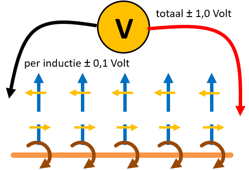
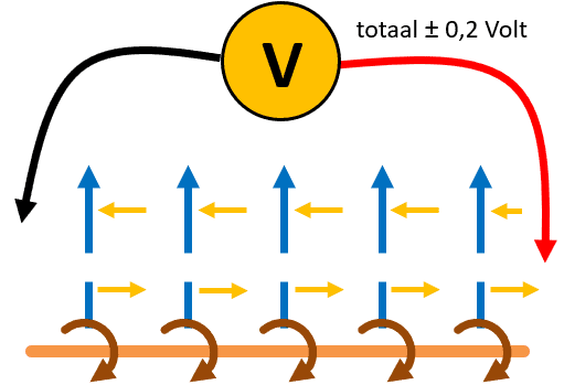
When CAN High and CAN Low are implemented as a twisted pair, both wires experience the same induction voltages from an external current-carrying cable. Because the wires are twisted, it constantly changes which wire is closest to the source of interference. As a result, the induction voltages largely cancel each other out and the original signal is better preserved.
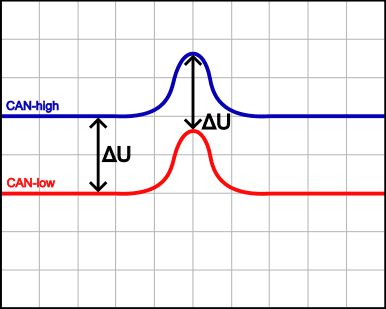
The scope image below shows how twisted pair wiring prevents interference. Because the induction voltages in both channel A (blue) and channel B (red) occur at the same level, the voltage difference (ΔU) remains equal to zero. The image confirms this: during the voltage spike, ΔU stays the same as during the normal signal behaviour.
Without twisted pair, the red spike can be inverted, causing the voltage difference (ΔU) to double and unintentionally be detected as a bit.
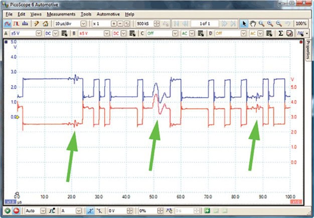
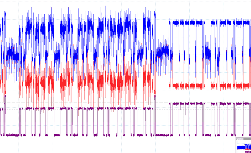
A signal with a lot of noise is hardly assessable visually. It is clear that in this example there is a fault in an ECU or in part of the network, which causes so much noise. In the next data block in the same scope image, the signal behaviour is normal. With the math channel (purple), the differential voltage between channel A and B can be displayed. This channel shows a correct trace. From this we can conclude that twisted pair ensures that, despite the strong noise, a reliable signal is maintained because no unintended voltage differences arise. The noise therefore has no effect on the data communication. As a result, the bits remain readable even when the signal quality at first sight seems completely lost.
Termination resistors:
In every high-speed CAN bus network, termination resistors are used. These are often located in the nodes at the ends of the CAN bus line (wire) or integrated into the wiring. Each of these resistors has a resistance of 120Ω (Ohm). The equivalent resistance is measured as 60Ω when measuring resistance on the wires.
These termination resistors are used for noise suppression; if they were not present, reflections would occur. The voltage signal travels through the CAN bus wire, reaches the end and bounces back. The latter is prevented. The voltage is absorbed by the resistor. Reflection could cause voltage signals to bounce back, which would affect the transmitted messages and subsequently cause the control units to generate faults.
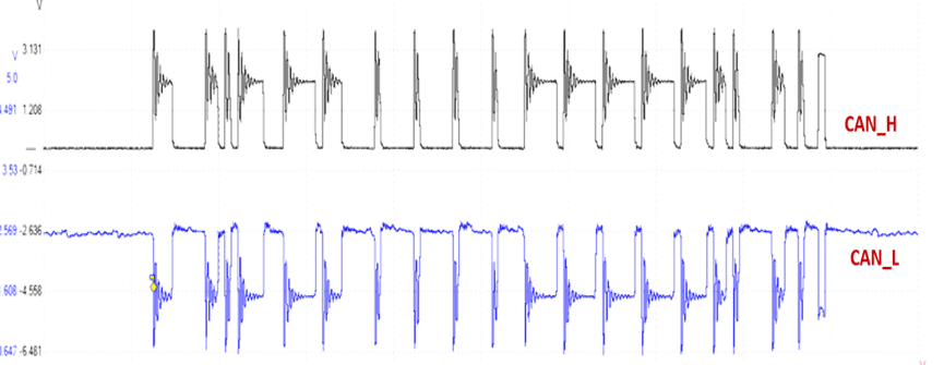
The image below shows the signal pattern of CAN-high and CAN-low where many oscillating reflections in the signal can be seen. The reflections occur because parts of the signal bounce back at the point where the termination is missing, due to missing or defective termination resistors. This causes overshoot, undershoot and ringing, as visible in the scope pattern. The worse the termination, the greater the reflection and the less reliable the signal. As a result, the signals no longer arrive reliably at the ECUs.
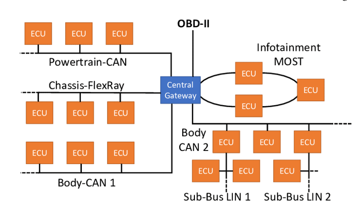
Gateway:
The car is equipped with a network of control units (nodes). The gateway connects various CAN bus networks (think of the interior, the engine / transmission and the chassis), the MOST bus, LIN bus and Flexray with each other, allowing all networks to communicate with one another. It is therefore essentially a junction between all networks. The differences in speed between the networks are unimportant for a gateway. Click here to go to the page where the operation and functions of the Gateway are described.
CAN bus diagnostics:
With a multimeter and an oscilloscope, diagnostics can be performed by measuring the resistance or voltage levels on the wires. Read all about this on the page CAN bus diagnostics.
Related page: