Introduction:
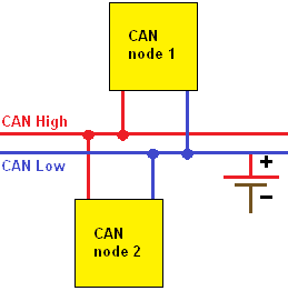
A fault in CAN bus communication can cause multiple vehicle functions to stop working, or complete control units to fail. If a CAN bus fault is suspected, a diagnosis can be made, among other things, by measuring the voltage levels on the wires.
The content of the CAN bus message is not important at first. We can take measurements on the CAN bus wires using both the multimeter and the oscilloscope. There is a limitation to measurements with the multimeter; when measuring voltages, only an average value is displayed. The multimeter is of limited use for measuring an open circuit or short circuit. To measure the voltage levels and assess whether the signal has a clean pattern, an oscilloscope is required.
How a CAN bus system works and how the messages are structured is explained on the page CAN bus. This page focuses on measuring the CAN bus with the oscilloscope and the multimeter and describes possible faults with their causes.
Diagnosing CAN bus signals low / medium speed:
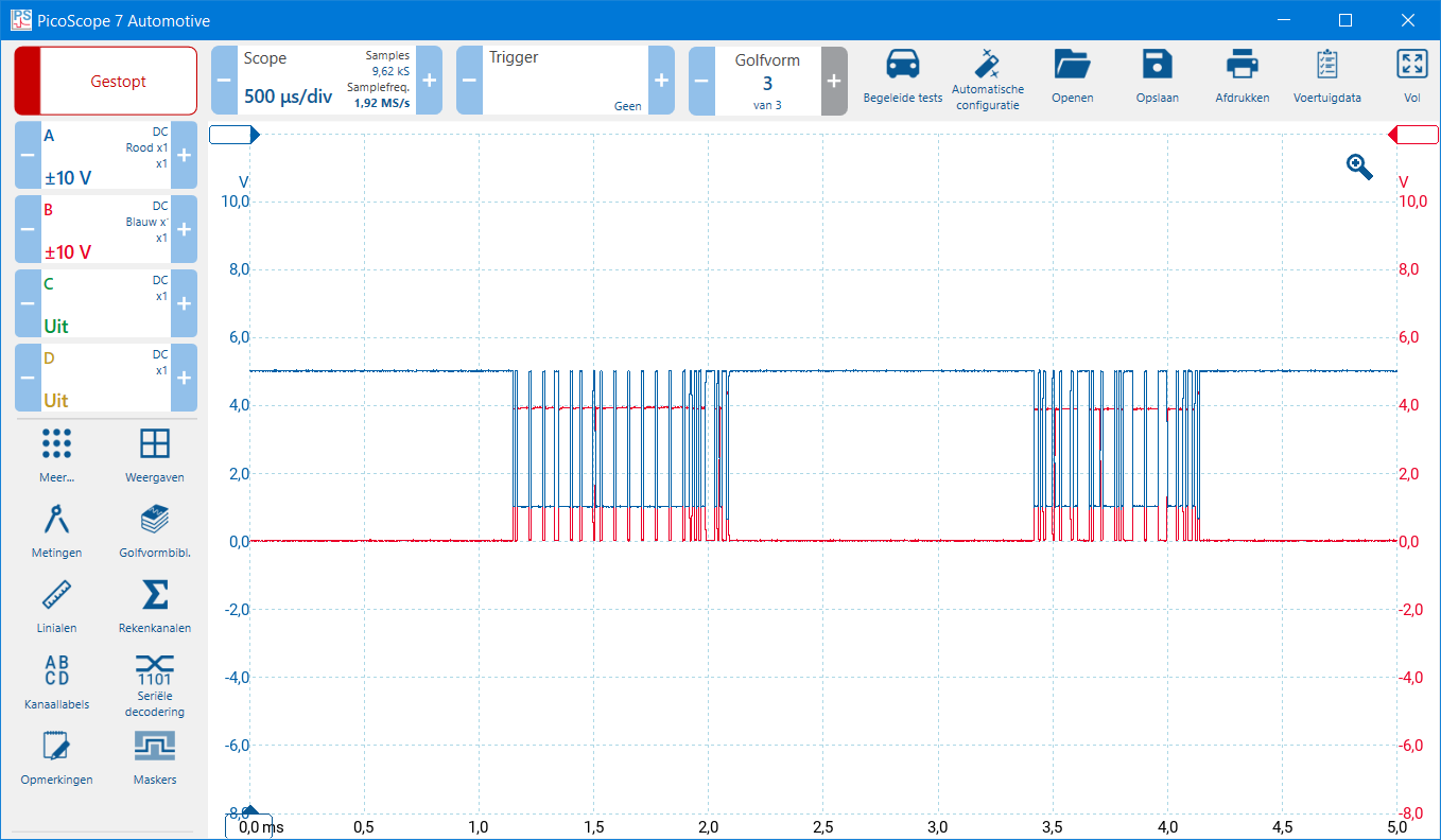
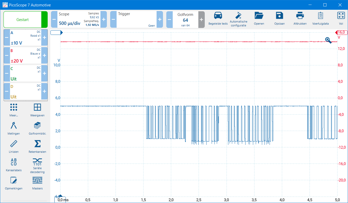
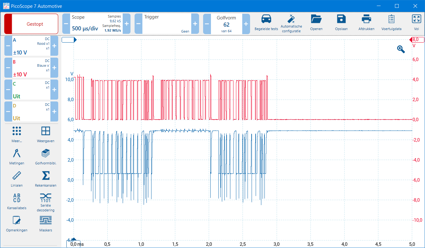
With a two-channel oscilloscope, CAN-high and CAN-low can be measured simultaneously relative to ground. The two scope images below show the CAN bus signal of the comfort bus. This is also called “low speed” or “medium speed”. We often find this network in comfort electronics, for example door electronics, BCM, the A/C control unit, and the instrument cluster. The voltages are as follows:
- CAN-low: at rest (recessive) 5 volts, active (dominant) 1 volt;
- CAN-high: at rest (recessive) 0 volts, active (dominant) 4 volts.
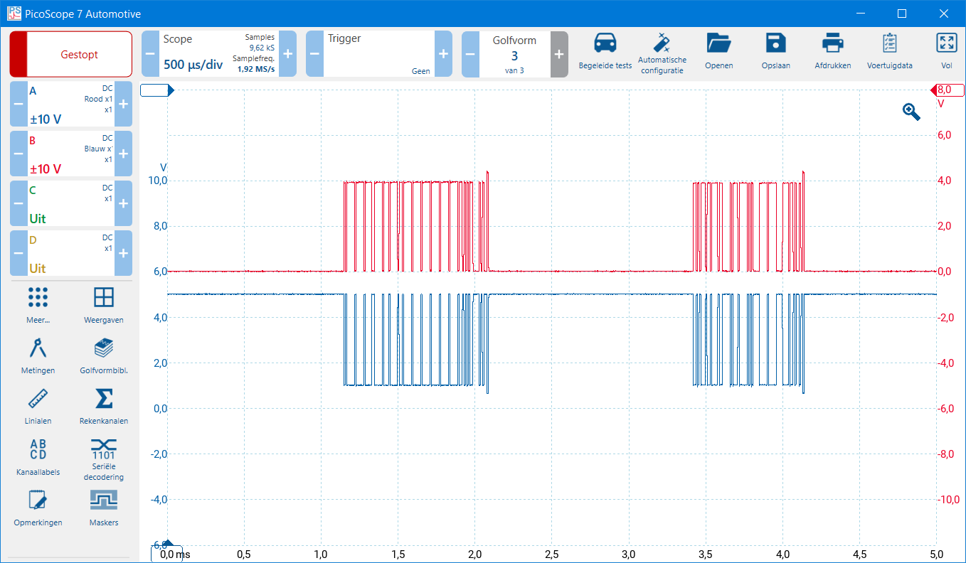
As soon as we set the zero lines of both measurement channels to the same height on the Y-axes, the signals overlap. For readability, it is therefore recommended to move the Y-axis of CAN-low upward. In the second image below, the zero lines have been shifted in height so that the voltage pattern of CAN-high and CAN-low can be compared properly.
Note: low- and medium-speed CAN networks are often not equipped with terminating resistors, unlike the high-speed CAN network. For that reason, the measurements performed when troubleshooting are also different. This paragraph shows the possible faults of the low and medium speed network, and the next paragraph shows those of the high-speed network.
CAN-high shorted to ground:
There is a short to ground on CAN-high. If the insulation is damaged, the wiring can make contact with the body, or there is a short circuit to ground inside an ECU.
In the measurement below, we see a constant voltage line on channel B that is 0 volts.
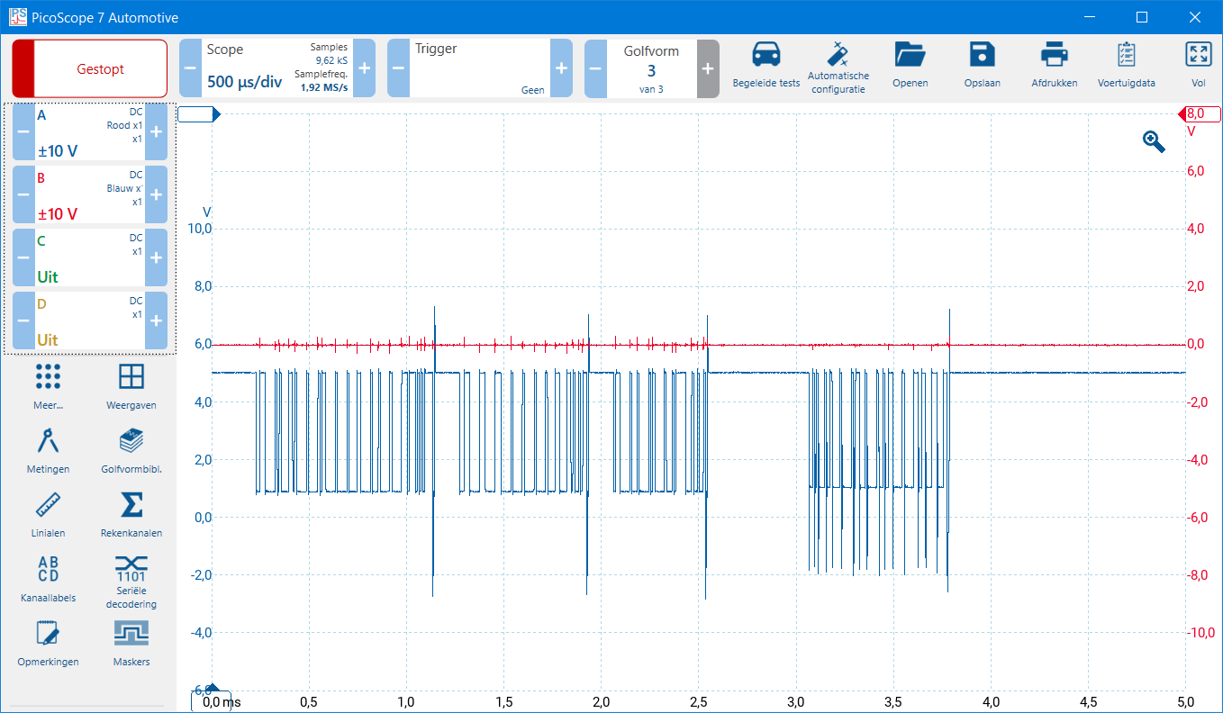
CAN-low shorted to ground:
There is a short to ground on CAN-low. If the insulation is damaged, the wiring can make contact with the body, or there is a short circuit to ground inside an ECU.
In the measurement below, we see a constant voltage line on channel A that is 0 volts.
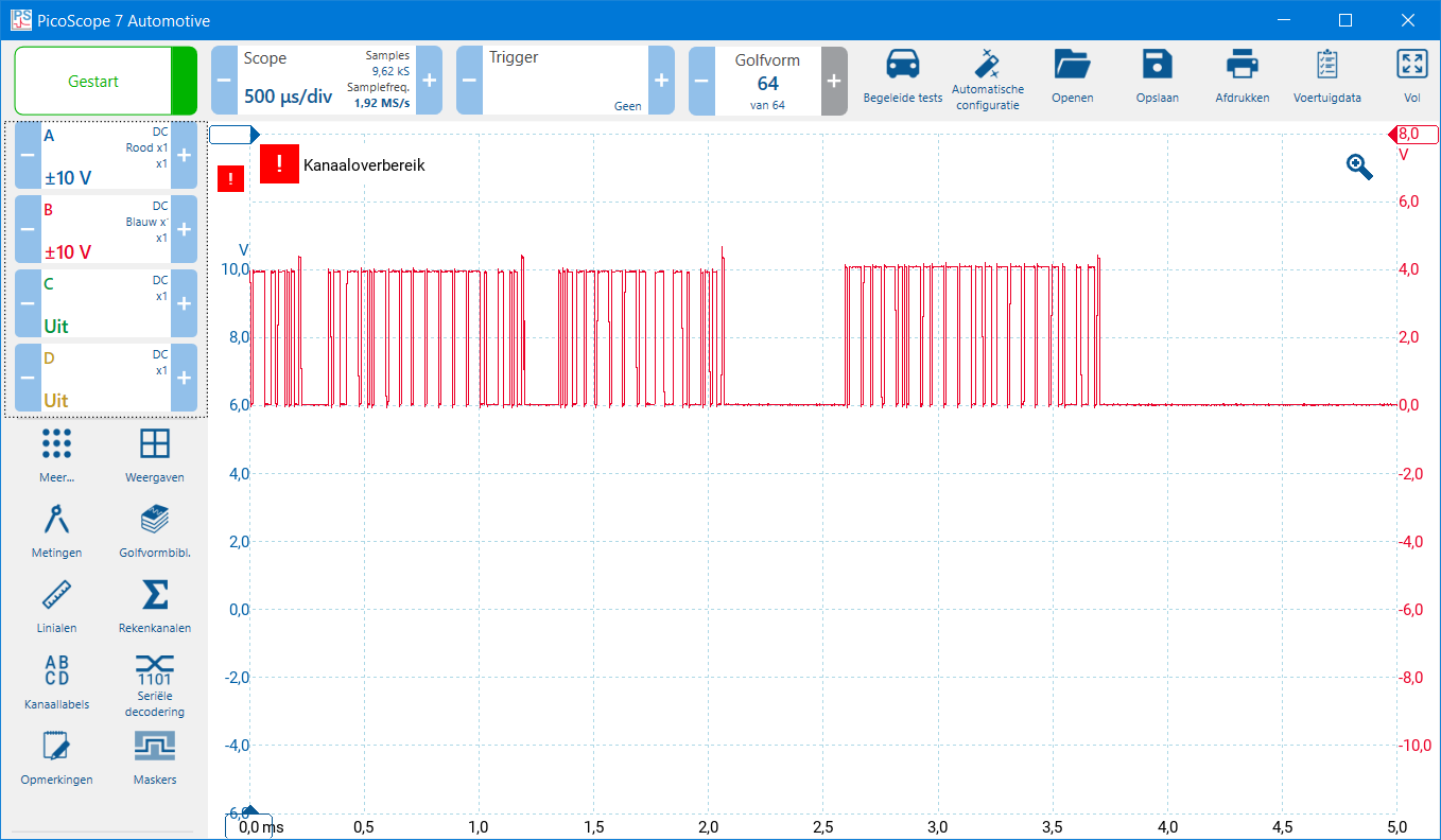
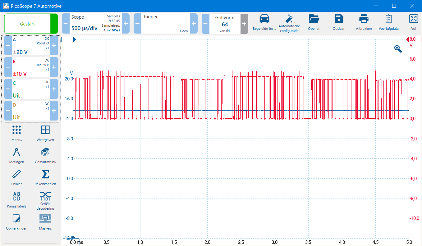
CAN-high shorted to power:
There is a short to power on CAN-high. If the insulation of multiple wires in a wiring harness is damaged, the wiring can make contact with each other, or there is a short circuit to power inside an ECU.
In the two measurements below, we see:
- Channel overrange: the voltage range of channel B (red) must be increased;
- On channel B we see (in the 20 V range) a constant voltage line that equals battery voltage.
CAN-low shorted to power:
There is a short to power on CAN-low. If the insulation of multiple wires in a wiring harness is damaged, the wiring can make contact with each other, or there is a short circuit to power inside an ECU.
In the two measurements below, we see:
- Channel overrange: the voltage range of channel A (blue) must be increased;
- On channel A we see (in the 20 V range) a constant voltage line that equals battery voltage.
CAN-high shorted to CAN-low:
CAN-low changes to the voltage pattern of CAN-high when they connect to each other. A short between CAN-high and CAN-low can occur in the wiring when the insulation of both CAN bus wires has worn through, or due to a defect in an ECU circuit board.
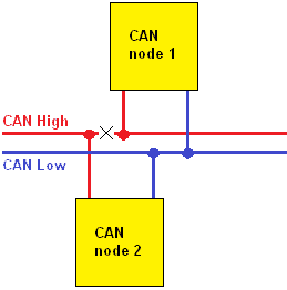
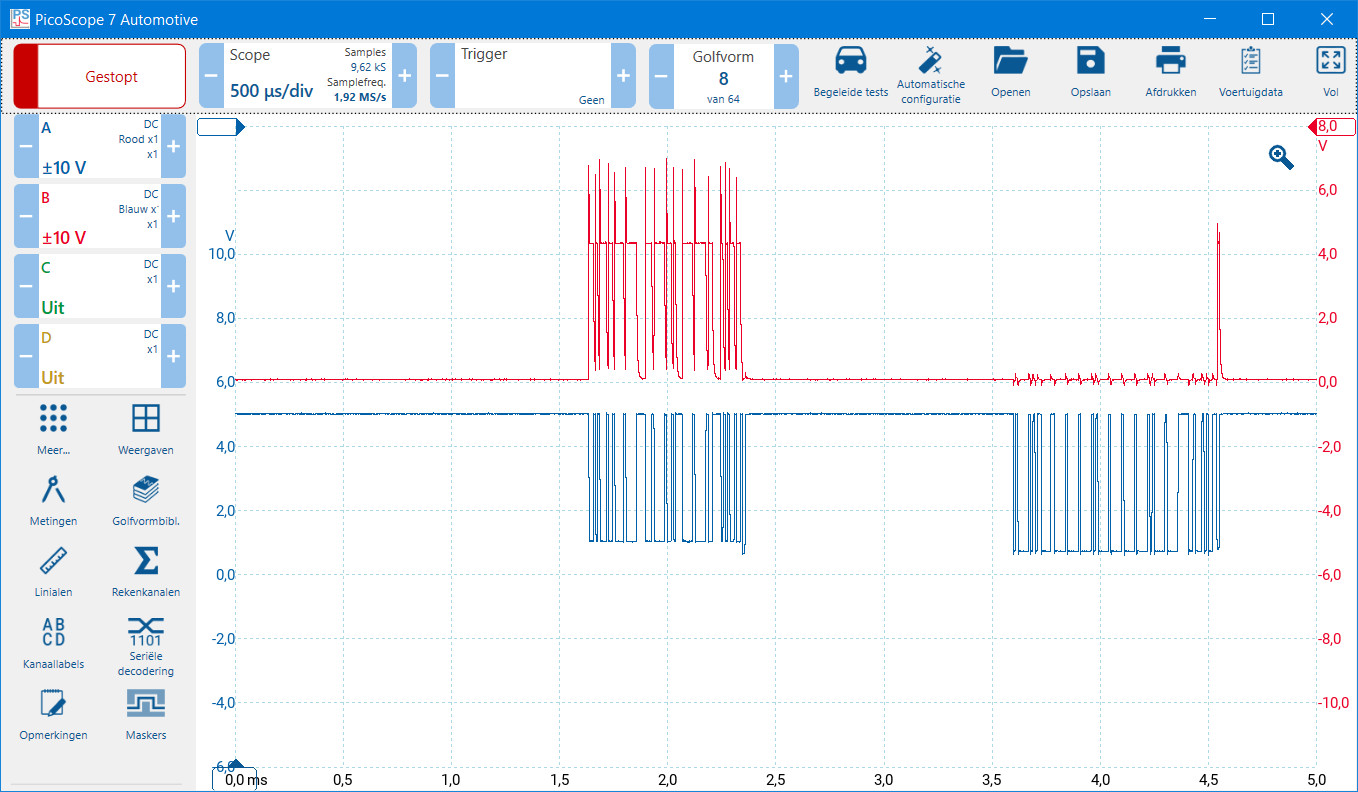
In the image below, we see the two-channel measurement in which CAN-high and CAN-low are shorted together.
Communication on CAN-high drops out occasionally:
Communication with one control unit on CAN-high is interrupted. This control unit sends and receives no more data via CAN-high, but CAN-low still functions. As a result, communication and reading out are still possible.
When the connector of the control unit in question is disconnected, the CAN-low data also drops out and no difference is visible anymore between CAN-high and CAN-low.
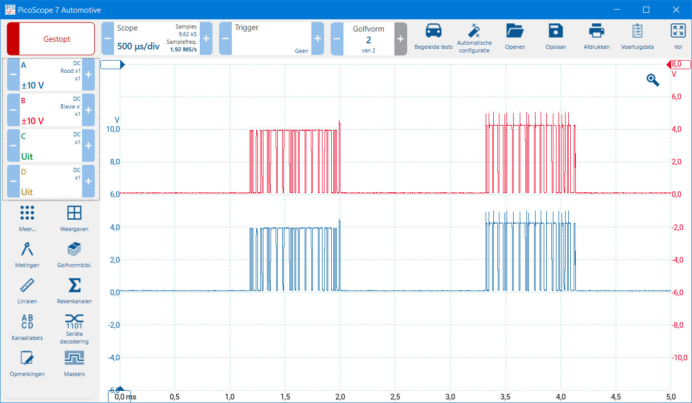
In the image below, we see that CAN-high remains recessive at one point, while data is still being transmitted on CAN-low.
Communication on CAN-low drops out occasionally:
Communication with one control unit on CAN-low is interrupted. This control unit sends and receives no more data via CAN-low, but CAN-high still functions. As a result, communication and reading out are still possible.
When the connector of the control unit in question is disconnected, the CAN-high data also drops out and no difference is visible anymore between CAN-high and CAN-low.
In the image below, we see that CAN-low remains recessive at one point, while data is still being transmitted on CAN-high.

Diagnosing CAN bus signals high speed:
ECUs for which a high communication speed is very important are equipped with a high-speed CAN network. This includes, for example, the internal combustion engine ECU, automatic transmission, ABS/ESP/EBS, and the airbags. A high-speed network is always equipped with terminating resistors. For that reason, faults in the wiring and ECUs also cause a different voltage pattern, which can sometimes make it harder to diagnose than with a comfort network. As always, a fault-free situation is shown first before we move on to faults.
The voltages of a high-speed network are as follows:
- CAN-high: at rest 2.5 volts, active 3.5;
- CAN-low: at rest 2.5 volts, active 1.5 volts.
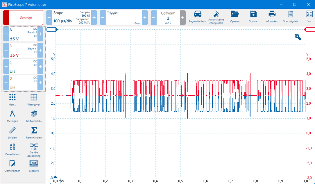
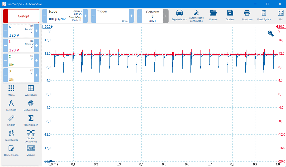
When CAN-high and CAN-low are both 2.5 volts, the bus is recessive (at rest). When CAN-high rises and CAN-low drops, the bus becomes dominant and a bit is formed. The image below shows a screenshot of a correct high-speed CAN bus signal.
If a signal like this is measured and a lot of noise is visible, it is recommended to remove the vehicle battery charger, connect the oscilloscope to vehicle ground (Automotive scopes have a “ground” connection on the rear for this), and use the sample rate to make the signal cleaner. The sample rate smooths the signal, so if it deviates too far from the standard value, the CAN signal can become too distorted.
For clarity: in the image below, CAN-high is red and CAN-low is blue.
CAN-high shorted to ground:
There is a short to ground on CAN-high. If the insulation is damaged, the wiring can make contact with the body, or there is a short circuit to ground inside an ECU.
In the measurement below we see that CAN-high (red) is exactly 0 volts because it is shorted to ground. CAN-low (blue) is slightly above the zero line. Zooming in on this signal would make this even clearer. Because CAN-high is exactly 0 volts and CAN-low is a few tenths of a volt higher, we can conclude that CAN-high is shorted to ground.
CAN-low shorted to ground:
There is a short to ground on CAN-low. If the insulation is damaged, the wiring can make contact with the body, or there is a short circuit to ground inside an ECU.
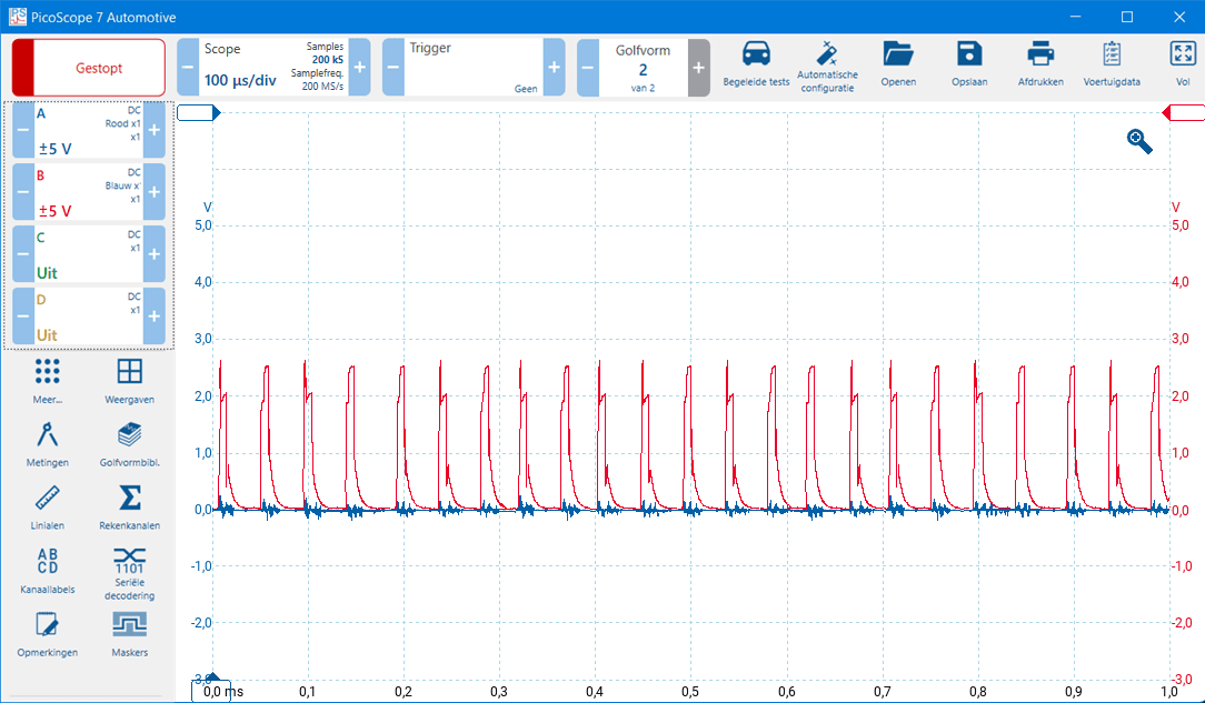
In the measurement below, we see that CAN-low is 0 volts. There is some noise visible, but we can disregard it. CAN-low is shorted to ground. We see the voltage line of CAN-high rise repeatedly, but that is not enough to start communication. The scope image also shows that CAN-low always has a lower voltage than CAN-high (red is always slightly higher than blue), which indicates that CAN-low is shorted to ground.
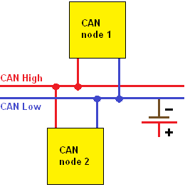
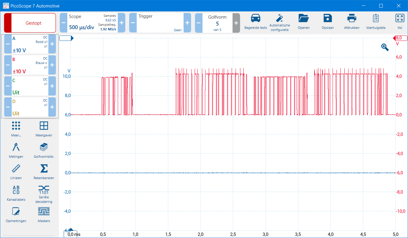
CAN-high shorted to power:
There is a short to power on CAN-high. If the insulation of multiple wires in a wiring harness is damaged, the wiring can make contact with each other, or there is a short circuit to power inside an ECU.
In the image below, we see a symptom that resembles the situation where CAN-low was shorted to ground. CAN-high (red) has risen to system voltage of around 12 volts. CAN-low (blue) has also increased in voltage and still tries to communicate by lowering the signal. Because communication does not start, the negative voltage spikes keep repeating.
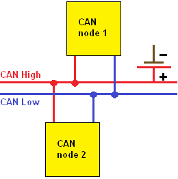
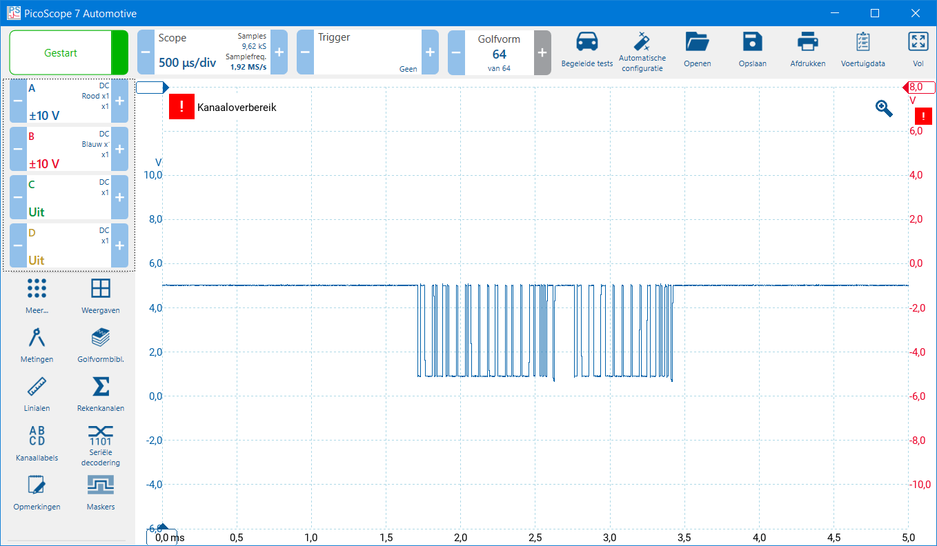
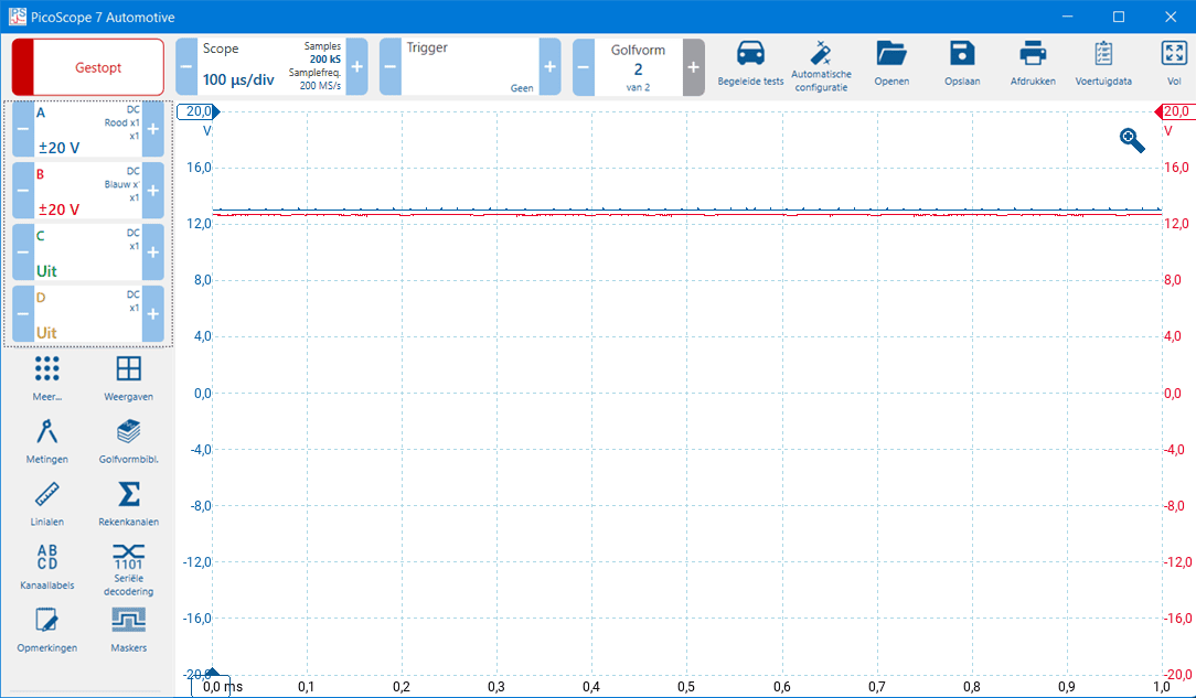
CAN-low shorted to power:
There is a short to power on CAN-low. If the insulation of multiple wires in a wiring harness is damaged, the wiring can make contact with each other, or there is a short circuit to power inside an ECU.
In the measurement below, we see that CAN-high and CAN-low are around 12 volts. However, the voltage of CAN-low is about 200 mV higher than CAN-high. CAN-low has lifted CAN-high upward. This indicates that CAN-low is shorted to power.
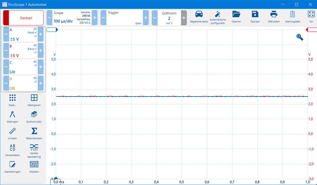
CAN-high shorted to CAN-low:
CAN-low changes to the voltage pattern of CAN-high when they connect to each other. A short between CAN-high and CAN-low can occur in the wiring when the insulation of both CAN bus wires has worn through, or due to a defect in an ECU circuit board.
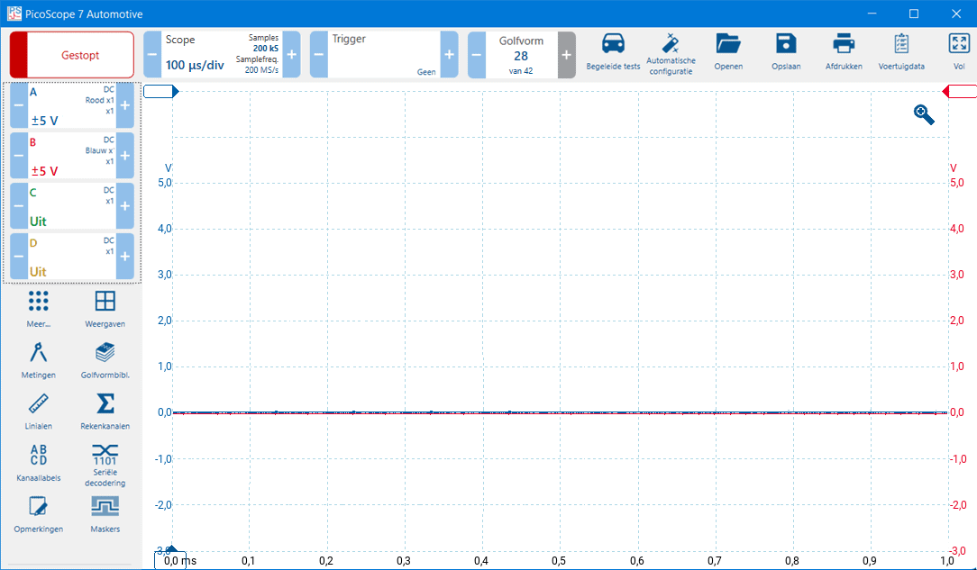
In the image below, we see the two-channel measurement in which CAN-high and CAN-low are shorted together. The voltage on both channels is 2.5 volts.
Diagnosing with the multimeter:
Measuring CAN bus voltage levels with a multimeter is not recommended. With voltages that change frequently in amplitude, the multimeter displays average values, so a proper diagnosis cannot be made. To measure the voltages, an oscilloscope should be used.
We can use the multimeter to measure the resistance of (only) a high-speed CAN network with terminating resistors. The measurements below show the ohmic resistance in three different situations: a correctly functioning system, an open wire, and a short circuit between CAN-high and CAN-low. In a low / medium (comfort) network, terminating resistors are rarely used, and these measurements cannot be performed.
Fault-free:
The CAN bus page describes that there are two terminating resistors present in the network. Both terminating resistors have a resistance of 120 ohms. In a fault-free system, we will measure an equivalent resistance of 60 ohms between CAN-high and CAN-low.
Note: we can only measure this if the power supply voltage of all control units is switched off!

Open circuit:
If there is an open circuit in a CAN-high or CAN-low wire, we no longer measure the 60-ohm equivalent resistance. In the image, we measure only the value of resistor R2 (120 ohms).

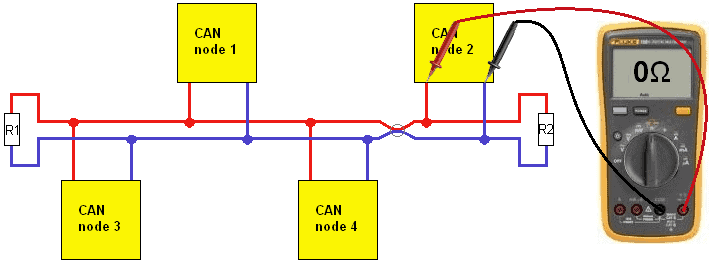
Short circuit:
If the CAN bus wires connect to each other (i.e., are shorted together), we measure a resistance value of approximately 0 ohms.
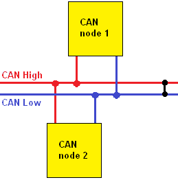
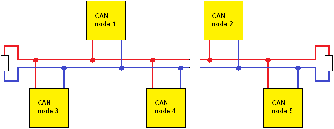
With the following fault, both CAN wires are open. A lot of interference (noise) will now be present on the bus. Nodes 1, 3, and 4 can communicate with each other provided the interference and reflection are not so great that the messages become distorted. Likewise, node 2 and 5 can communicate with each other subject to the same issue.
Some CAN networks also function when one wire is open. Fault codes will be stored and the driver will be informed by warning lights and messages from various systems. These are networks equipped with a Fault Tolerante CAN transceiver. Depending on the transceiver used, different types of faults can occur without communication between the nodes being lost. Even with the faults mentioned earlier involving shorts to power and ground, these CAN transceivers can function normally (of course with various fault messages).