Crankcase ventilation in general:
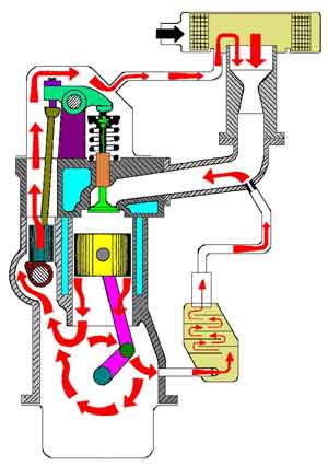
Crankcase ventilation is a system that discharges vapours from the crankcase to the intake manifold of the engine. In the oil pan there is not only engine oil, but also air. This air is mixed with oil vapours and a minimal amount of exhaust gases that pass the piston rings and end up in the crankcase. We call these the “blow-by” gases. These vapours must not be released into the open air. If this is deliberately done, as used to be the case with old engines, we call that Negative Crankcase Ventilation. However, this is harmful to the environment, as the vapours consist of combustion residues, water vapour and petrol vapour.
Nowadays, the vapours are routed through hoses and pipes to the intake tract of the engine (visible in the image alongside). The crankcase vapours are thus drawn in by the engine and subsequently take part in the combustion process. After they have been burned, they are no longer harmful. The completely closed crankcase ventilation system is called “Positive Crankcase Ventilation”, abbreviated as PCV. The positive crankcase ventilation system is fitted with a so‑called PCV valve that regulates the pressure to the crankcase.
Crankcase ventilation and crankcase breather systems are often confused. There is a fundamental difference between crankcase ventilation and a crankcase breather system:
- with crankcase ventilation, the crankcase vapour is discharged and fresh air is supplied;
- with a crankcase breather system, only the crankcase vapours are extracted.
Crankcase ventilation valve:
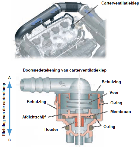
The crankcase ventilation valve is both a non-return valve and a pressure regulating valve, which discharges the overpressure of the crankcase ventilation to the intake of the engine, but closes in the opposite direction. In most cases, the crankcase ventilation valve is designed as a spring-loaded diaphragm valve that keeps the vacuum in the crankcase at approximately 0.02 to 0.03 bar relative to the ambient air pressure.
When this PCV valve opens, the water vapour and blow-by gases are absorbed into the intake air and burned along in the cylinder.
The crankcase ventilation valve is connected to the outside air on one side and to the intake manifold on the other side. The aim is to maintain a low, constant pressure in the crankcase with varying pressures in the intake manifold.
- At idle speed, the pressure in the intake manifold is low (vacuum). The valve is almost closed;
- When the throttle is opened, the throttle valve is slightly opened and the air pressure in the intake manifold rises (less vacuum). The valve opens further.
When the valve opens, the sealing disc moves upwards against the spring force. This increases the passage, allowing more crankcase vapours to be discharged to the intake.
Blow-by gases:
The gases that enter the crankcase from the combustion chamber are called blow-by gases. Blow-by gases can enter the crankcase in many ways. Factors such as piston clearance, the condition of the piston rings, and the ovality and wear of the cylinder wall have the greatest influence on the amount of blow-by gases produced by an engine.
During combustion, about one kg of water vapour per litre of fuel is produced, part of which passes the piston rings and ends up in the crankcase.
During the warm-up phase of a cold engine and with a rich mixture under acceleration, the most blow-by gases are produced, which causes unburned or partially burned fuel to end up in the crankcase. Blow-by gases consist of 10 to 40% oil and the rest of gases such as H20, CO, CO2, HC and NOx.
Types of crankcase ventilation and crankcase breather systems:
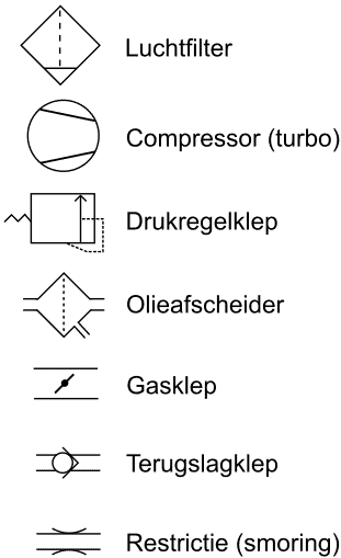
The illustrations show a section of the engine block in which the type of crankcase breather system can be identified. The components of the crankcase breather system are indicated using pneumatic symbols.
The legend shows the meanings of the symbols.
Each type of crankcase breather system is numbered (from 1 to 7).
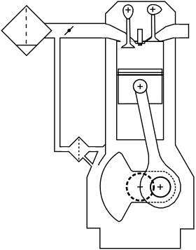
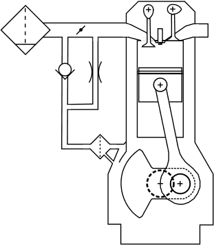
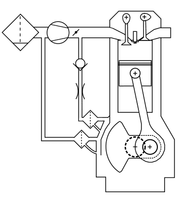
1. unregulated crankcase breather system with outlet before the throttle valve:
The crankcase breather system consists of an oil separator and a hose to the air hose between the air filter and the throttle valve. This is the simplest version of the crankcase breather system we come across in passenger cars. There are many disadvantages to this design:
– the crankcase vapours can contaminate the mass air flow sensor;
– the vacuum in the crankcase depends on the air filter resistance.
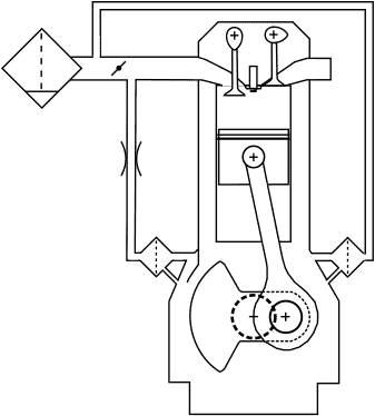
2. crankcase breather system with non-return valve before, and restriction after the throttle valve:
Compared to number 1 (above), there is better ventilation, because there is a better airflow across the throttle valve under part load. A disadvantage is that the design is more complicated than number 1.
3. crankcase ventilation with change of flow direction in the ventilation line:
The major advantage is that there is actual ventilation in the crankcase, and not just venting. Disadvantages are that a second oil separator is needed and that the airflow in the oil separator reverses.
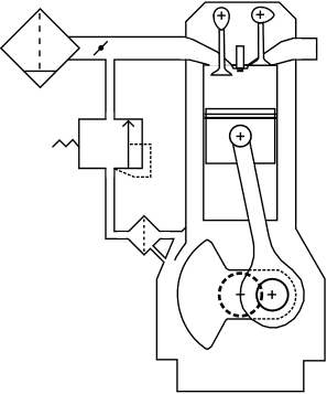
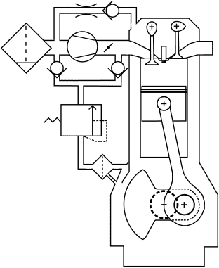
4. regulated crankcase breather system with outlet after the throttle valve:
Because this version is located after the throttle valve, there is more vacuum in the crankcase breather system (a stronger suction effect). Therefore, a pressure regulator is required. Between the oil separator and the intake pipe there is a pressure regulator that only opens at a certain crankcase pressure. Without overpressure in the crankcase, the pressure regulator remains closed.
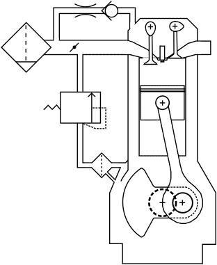
5. regulated crankcase ventilation system with outlet before the throttle valve:
In this version we also see the pressure regulator. The additional feature in this system is the hose between the air intake pipe in front of the throttle valve and the connection on the valve cover. This makes ventilation possible. The disadvantage is that there is false air across the throttle valve.
6. unregulated crankcase breather system of a turbocharged engine:
Between the throttle valve and the intake manifold there is a non-return valve in the crankcase breather hose. This prevents the turbo from blowing an overpressure into the crankcase ventilation system. Under full-load conditions, this overpressure valve would remain closed and the crankcase pressure would rise too high. For that reason, an additional oil separator with a hose is attached to the suction side of the turbo.
7. regulated crankcase ventilation system of a turbocharged engine:
The hose to the valve cover makes crankcase ventilation possible. The pressure regulating valve with two non-return valves enables a higher vacuum for the oil separator. The disadvantage is that this system is complex.
Oil separators:
To prevent engine oil from being drawn into the intake manifold via the crankcase ventilation together with the blow‑by gases, manufacturers use oil separators. Without an oil separator, components such as the mass air flow sensor, turbo, valves and the catalytic converter or diesel particulate filter could become contaminated or damaged. As the name already suggests, the oil separator separates air and oil residues from each other. Oil separators exist in different designs: the cyclone, labyrinth and electrolytic oil separator. These three designs are described in the following paragraphs.
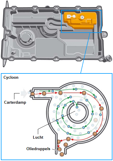
Cyclone oil separator:
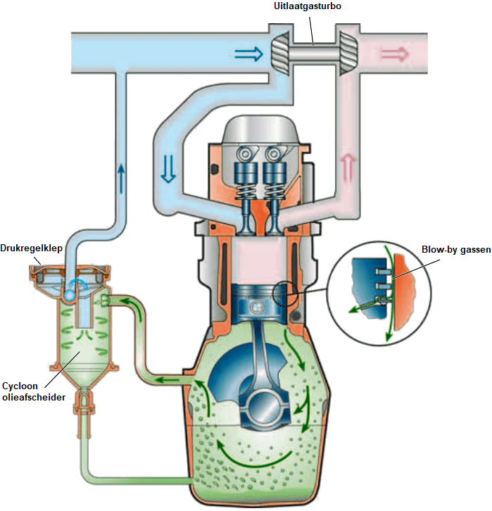
The cyclone oil separator separates the oil and air in the crankcase fumes by setting the air in a swirling motion. Due to the centrifugal force that is created during the swirling, the heavier oil particles are thrown against the inside of the housing.
The oil droplets that remain are returned to the crankcase via a hose. The air pushes the pressure control valve upwards against the spring force and is routed to the engine intake. In the image we can see that the turbo draws in this air.
The pressure control valve closes when a vacuum threatens to form in the crankcase, for example when the turbo is drawing in a lot of air. Excessive vacuum in the crankcase could damage gaskets and seals.
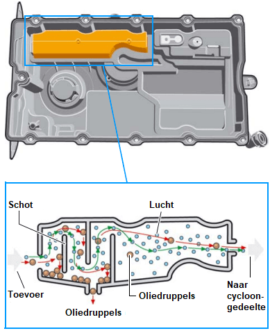
Labyrinth oil separator:
A labyrinth oil separator is often combined with a cyclone separator. In the labyrinth oil separator, the crankcase fumes collide with the baffle plates. The oil droplets are separated from the air and fall back into the crankcase. The remaining oil residues are then separated from the vapor in the cyclone separator.
With increased crankcase pressure and an excessively large amount of crankcase fumes, for example as a result of excessive wear of the piston rings, the pressure relief valve opens to prevent the crankcase pressure from rising too high.
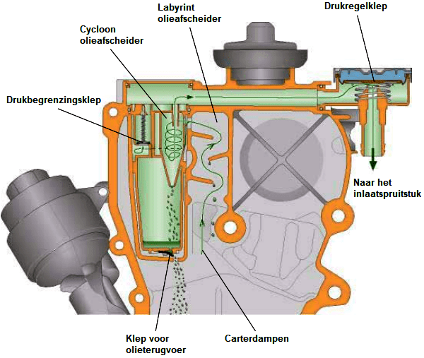
The images below show a valve cover from a 2.0 TDI VW engine. Both types of oil separators are mounted in the valve cover.
The images below show the positions of the labyrinth and cyclone oil separators. The crankcase vapor enters the labyrinth (left). In the labyrinth, the coarse oil residues are separated from the flowing air. From the labyrinth, the crankcase vapor enters the cyclone section to remove the last oil residues from the air.
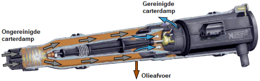
Electrostatic oil separator:
The previously mentioned oil separators do not achieve 100% effective separation. When the crankcase vapor passes through these types of oil separator at low speed, as can occur at low engine speed, small oil droplets still remain in the vapor. With the electrostatic oil separator, these small droplets are also removed from the crankcase fumes. The cleaned crankcase vapor contains less than one percent of the oil that entered with the unfiltered crankcase vapor.
The following image shows the electrostatic oil separator.
By means of high voltage, even the smallest oil droplets are magnetized so that they stick to the separator. In this way, the oil is separated from the air.
Inside the housing there is a transformer that converts the on‑board voltage of 12 or 24 volts (in a passenger car or commercial vehicle) into a high voltage of 9 to 12 kilovolts.
Electric heating for the crankcase ventilation:
Water vapor is present in the crankcase fumes. In the paragraph “blow‑by gases” it was already described that per liter of fuel about one kg of water vapor is released, part of which ends up in the crankcase past the piston rings. In a cold engine where the temperature in the crankcase ventilation is less than 70 degrees Celsius, the water vapor will condense into liquid water. With many cold starts and short trips, a large amount of water accumulates in the engine block.
While the engine is running, part of the moisture evaporates and the vapor is discharged through the crankcase ventilation. The crankcase vapor condenses on the colder parts of the engine components, including the crankcase ventilation hoses. To prevent the vapor in the hose from freezing at low ambient temperatures, many car manufacturers install one or more heating elements in a crankcase ventilation hose.
The heater is activated by the ECU during a cold start.
In engines without a heating element, or where the heating is not functioning, the ventilation hose may freeze. A blockage then forms at that point. The crankcase pressure then becomes considerably higher. As a result of the increased crankcase pressure, oil leaks can occur via the crankshaft oil seal or gaskets (valve cover or oil pan gasket).
In engines that do not reach operating temperature often enough, the water in the oil pan can freeze. Because oil floats on water, the ice blocks the oil supply in the oil strainer. Due to the low oil pressure, engine damage occurs. The electric heating described in this paragraph does not provide a solution for this: the heating prevents freezing of the crankcase ventilation hoses which may be located at the top of the engine compartment. To prevent large amounts of water from accumulating in the crankcase, it is advisable to let the engine warm up properly by making long trips frequently, not postponing maintenance intervals and avoiding short trips of only a few kilometres as much as possible.
Common problems with crankcase ventilation:
- Clogged crankcase ventilation: a high pressure builds up in the crankcase and that impedes the operation of the engine. In engines with a great deal of white sludge (oil residues with moisture, caused by always driving short distances where the engine never reaches operating temperature, or by a defective thermostat) the crankcase ventilation can become completely clogged. The hoses then fill up with sludge and can freeze in winter (because white sludge largely consists of moisture). When this happens, the hoses can spontaneously burst apart.
- Cracked hoses: oil affects rubber. Crankcase fumes contain oil residues and the hoses to the intake are often made of rubber. As these hoses get older, they can crack. These hoses often already feel like chewing gum beforehand, which is an indication that they are due for replacement.
- A cracked crankcase ventilation hose can cause an unpleasant oil smell in the engine compartment and thus also in the interior. The engine will also draw in unmetered (false) air, because the extra air drawn in has not been measured by the mass air flow sensor. Due to the excess air, the engine may start to run irregularly, consume more fuel and the check engine light may come on.
- Engine contamination: despite oil separators, crankcase fumes can still contain small oil droplets. This can contaminate the engine’s intake tract, including the throttle body and intake valves.
- Increased crankcase pressure: This is not a problem with the crankcase ventilation itself, but it is noticeable via the ventilation. When a lot of air is being blown through the crankcase ventilation, one or more (compression) piston rings or the cylinder wall may be damaged. During the compression stroke, the mixture leaks past the piston rings into the crankcase (blow‑by). To be sure whether the cause lies with the piston rings, a compression test or a cylinder leak‑down test must be carried out. In an engine suffering from this, the engine oil will become contaminated and age more quickly due to the fuel and combustion gases.