Introduction to disc brakes:
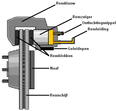
The disc of the disc brake is mounted between the hub and the rim. The brake disc therefore always rotates with the wheel. Brake pads are fitted on both sides of the brake disc. When braking, the brake linings are pressed against the disc, causing the rotational speed of the brake disc to decrease. Friction between the brake lining and the brake disc generates heat.
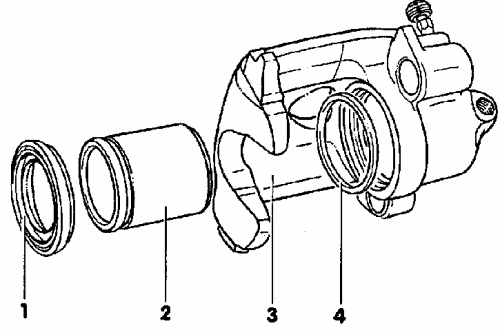
The illustration shows an overview of the disc brake. When braking, the brake fluid is forced through the brake line into the large (indicated in yellow) chamber behind the brake piston. Because brake fluid is incompressible, the build-up of pressure will cause the brake piston to move outward. At that moment the brake pad is pressed against the brake disc.
The caliper in the illustration is of the “floating type”. This means that the caliper can slide back and forth on guide pins, because there is only one brake piston. The next section describes the differences between a floating and a fixed caliper.
Types of disc brakes:
Disc brakes can be designed with either a floating or a fixed caliper. This section describes how both types work.
Disc brake with floating caliper:
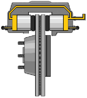
With a floating caliper, the brake operates with a single brake piston. When braking, the piston first presses the inner brake pad (on the piston side) against the brake disc. As a result, the caliper will shift to the right. This is possible thanks to the two guide pins over which the caliper can slide. Because the caliper moves along the guide pin while braking, the outer brake pad is also pushed against the disc. The disadvantage of the floating caliper is that the inner brake pad often wears faster than the outer one, because the outer pad is often pressed against the brake disc with slightly less force. That is why it is always very important, especially during inspection, to look closely at the inner brake pad. Where the outer brake pad may still be 5 mm, the inner pad may already be 3 mm.
Disc brake with fixed caliper:
In this design, there are two brake pistons in the caliper, one on each side of the disc. The caliper is mounted on the steering knuckle and does not move when the brake is applied, unlike the floating caliper. When the brake pedal is operated, the brake fluid presses against both pistons. The advantage of this system is that both brake pads are pressed against the brake disc with the same force.
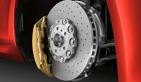
Carbon ceramic brakes:
With conventional brake discs, the temperature can rise very high during prolonged, hard braking. This can result in brake fade, causing the braking power to decrease. This is especially a problem in motorsport and with sports cars.
For this reason, car manufacturers have increasingly used carbon ceramic brakes since around 2000. The temperature of carbon ceramic brake discs also becomes very high (up to 1350°C), but at high temperatures the friction characteristics remain stable. So no brake fade occurs at high temperatures.
Braking performance is optimal when the brakes are warmed up.
The material of these brake discs is very hard. As a result, the brake discs last much longer than conventional brake discs. Care must be taken when disassembling / assembling, for example, the wheels; if the wheel is bumped against the brake disc, the discs can easily be damaged.
Another advantage of carbon ceramic brake discs compared to conventional brake discs is their low weight. A carbon ceramic brake disc weighs up to 70% less than a “normal” brake disc. This benefits the unsprung mass, which should be kept as low as possible for optimal driving characteristics of the car.
The downside of this type of brake disc is the price; the surcharge for ceramic brakes on a new car can be more than ten thousand euros.
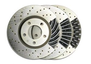
Ventilated and drilled brake discs:
The illustration shows brake discs that are both ventilated and drilled. The openings in the brake discs allow air to flow through them, so that the discs can cool down more quickly after braking.
Release of the brake pads:
When braking stops, the brake pads must release from the brake disc again. Around the brake piston there is a rubber ring (number 4 in the illustration below) that seals between the piston and the brake cylinder. During braking the ring deforms. When the brake pedal is released, the rubber ring returns to its original shape. This pulls the piston back slightly, allowing the pads to release from the disc. With this design there is almost always some clearance between the brake pad and the disc. As the pads wear, the piston shifts within the rubber ring.
The dust boot is indicated by number 1. The dust boot prevents moisture and dirt from entering the caliper and prevents brake fluid from leaking out of the caliper.
Measuring brake disc thickness:
Brake discs always wear through use and will last for one or two sets of brake pads. As they wear, the brake disc becomes thinner. Car manufacturers define a limit to how far a brake disc may be worn. This is stated in the vehicle documentation as the “minimum brake disc thickness”.
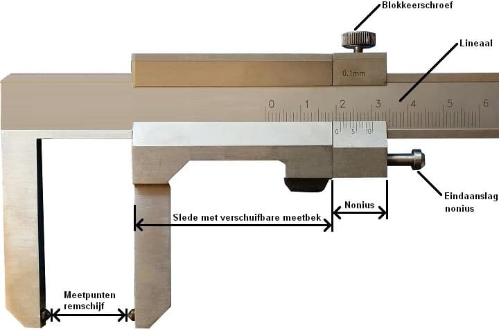
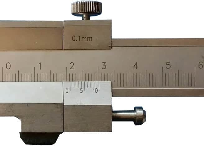
With a special brake disc thickness caliper, the thickness of the brake discs can be determined. Measuring brake disc thickness cannot be done with a standard caliper, because a normal caliper has flat jaws and therefore measures the thickness of the (rust) edges on the disc. That is not the intention, because only the thickness of the area where the pads wear into the disc is of interest. With a brake disc caliper, the contact surface where the pad touches the brake disc is measured. This can be seen in the illustration below and is explained underneath it.
Between the two jaws are lugs that are placed against the running surface of the brake discs, i.e. the areas where the pads contact the discs. The lugs protrude so that the thicker (rust) edge of the disc does not interfere with the measurement. To move the caliper over the rust edge, the vernier (which is later read) can be slid. During measurement, the locking screw must be tightened so that the vernier can no longer move.
The illustration shows such a caliper.
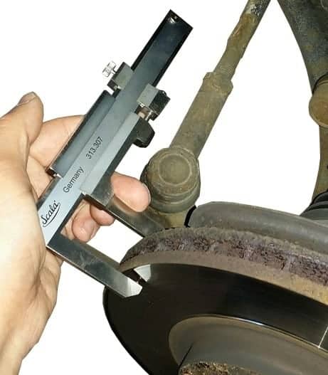
When measuring, the jaws with the lugs must be pressed against the brake disc (see the illustration below). The vernier must be moved to the end stop, i.e. fully to the right until it can no longer move. Then the locking screw must be tightened so that the vernier can no longer slide back and forth over the ruler. At this point the caliper can be removed from the brake disc. The jaws can be moved to pass over the (rust) edge because the vernier is locked in the outermost position. The position of the jaws has no influence on the value indicated by the vernier on the ruler.
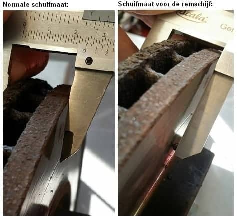
After removing the caliper, the values on the vernier and the ruler can be read. The illustration below is an enlargement of the measurement of the brake disc measured above. The indicated dimension is 21.2 mm.
For the vehicle whose brake disc was measured, the minimum brake disc thickness is 22.0 mm. The measured value, 21.2 mm, is therefore lower than the minimum value. The brake discs therefore need to be replaced. If the measured value had been higher than the minimum brake disc thickness, the discs would still be thick enough to fit another new set of brake pads.
Brief explanation of reading the caliper:
On the ruler, to the left of the 2 there is a long line. This is the 2 cm line, or 20 mm.
The 0 on the vernier is slightly past 21 mm. That means the dimension is slightly larger than 21 mm, so there will be a digit after the decimal point. To determine that digit, you need to look at which line on the vernier coincides with a line on the ruler. Counting from 0, this is the second line, so the exact measured value is 21.2 mm.
The page mechanical measuring tools provides more information on mechanical measurements.
Warped brake disc:
When the driver brakes the car hard, the parts of the braking system become very hot. During prolonged braking, brake discs can reach temperatures of more than 300° Celsius. If the driver then keeps the brake pedal pressed while the car is stationary, the pads are pressed against a stationary disc. The brake disc will cool unevenly; this means that the disc cools down across the entire surface except at the point where the pads touch the disc.
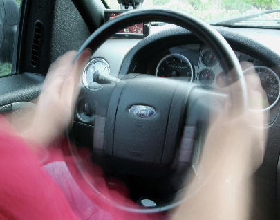
Due to the temperature difference, the brake disc can deform slightly, causing it to become “warped”. The steering wheel will then start to vibrate when the brake pedal is operated. The vibration can even become so strong that it can be felt throughout the entire car.
Another way warped brake discs can occur is when, after braking for a considerable distance, the car is driven through a puddle of water. The water that reaches the disc can cause uneven cooling, which can deform the brake disc.
The next section describes how brake disc runout can be measured.
Measuring brake disc runout:
If the steering wheel of the car vibrates while braking, warped brake discs may be the cause. Often, the vibration is already noticeable at low vehicle speeds. To rule out the possibility that the vibration is caused by other suspension components, the runout of the brake discs can be measured.
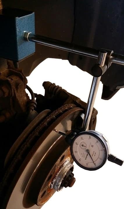
To measure the runout of the brake disc, a fixture with a magnet is mounted on a fixed part of the vehicle (for example, the shock absorber). A dial gauge is mounted on the end, with the tip placed against the brake disc. This is shown in the illustration below.
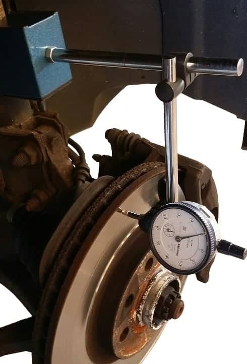
After the dial gauge has been set to 0 and the fixture is securely mounted, the brake disc can be rotated. The needle of the dial gauge will indicate how far the disc moves in and out. In the illustration below you can see that at a certain point the dial gauge indicates 20. This 20 stands for 0.20 mm. For this vehicle, the factory data states that the maximum permissible brake disc runout is 0.1 mm. In this case the runout is 0.1 mm more than permitted, so there is a warped brake disc.
In some cases the wheel hub can also be warped. To be sure that only the discs are causing the vibration, the brake disc can be removed from the hub and the same measurement can be performed on the hub. If the needle of the dial gauge then also moves too far, the hub, and thus also the wheel bearing, must be replaced together with the brake disc.
Related page: