Introduction:
The parking brake is often called the “handbrake”, because in many cars the lever has to be pulled by hand. The image below shows the parking brake with a handbrake lever, brake cables and drum brakes. When the driver moves the handbrake lever upwards, an internal mechanism locks the lever and keeps it in the raised position. When the lever is operated, the front handbrake cable is pulled tight. The left and right handbrake cables are connected to the front handbrake cable by means of an equalizer bracket. The equalizer bracket makes it possible to compensate for play; think of a stretched handbrake cable or an incorrectly adjusted mechanism in the brake drum. If one cable is longer than the other for that reason, the equalizer bracket will tilt. Nevertheless, both brake cables will be tightened equally when operating the handbrake lever.
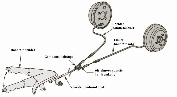
The front handbrake cable is connected to the equalizer bracket by means of an adjusting nut. We can turn this adjusting nut for the following reasons:
- Adjusting the handbrake. This may be necessary if the handbrake lever has to be pulled up, for example, eight notches before the brakes are locked.
- Removing handbrake cables, the handbrake mechanism in brake drums or the brake caliper. Dismantling certain parts without slackening the cables is often not possible.
The explanation above relates to the common cable-operated parking brake. Nowadays there are also other versions, such as parking brakes operated by the foot and the electric parking brake. This page describes the different versions of the parking brake.
Drum brake as parking brake:
When a car is equipped with drum brakes on the rear axle, a parking brake mechanism is built into them. When the handbrake cable is pulled (see the red arrow to the left of the cable), the dark blue lever in the image is pulled to the left at the bottom. The lever pivots in the right (light blue) brake shoe and pushes the brake lining against the (yellow) brake drum.
The white spacer is connected to the dark blue lever and the left (light blue) brake shoe. The movement of the lever is transmitted to it, so that the brake lining of this brake shoe is also pressed against the brake drum.
When the parking brake cable is released, the spring on the handbrake cable pushes the inner cable back to its initial position. The springs on the brake shoes pull the brake shoes and linings back towards each other, so that the linings come away from the brake drum.
Due to wear of the brake drum, the diameter on the inside becomes slightly larger. The brake shoes therefore move further outwards in order to contact the brake drum. During maintenance and repairs, we must remove the brake drum from the axle. In most cases it is not possible to remove the drum without backing off the brake shoes.
The mechanism contains a star wheel or a pawl that must be turned back or moved using a flat screwdriver. The image shows the movement of the screwdriver to turn the star wheel. Turning the star wheel in one direction causes the shoes to move towards each other; the spacer becomes shorter and the brake shoe springs pull the shoes together. Once the star wheel has been turned back far enough, the brake drum can be removed.
During assembly, we must of course turn the star wheel in the opposite direction so that the shoes return to the correct position.
Disc brake as parking brake:
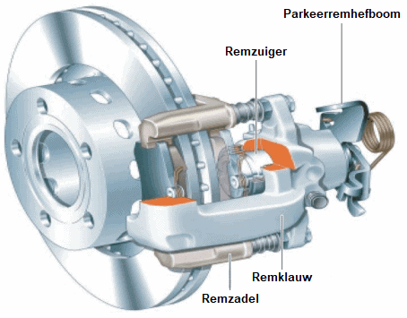
A car that is equipped with rear disc brakes may be fitted with a parking brake mechanism. In the following image, the brake caliper with the parking brake lever can be seen. The lever is connected via a cable to the parking brake lever in the interior. When the driver operates the lever, the lever on the brake caliper rotates and moves an internal mechanism. The parking brake uses the same brake piston as the service brake, which is operated by the hydraulic brake circuit. When the brake is applied, the brake piston presses the inner brake pad against the brake disc. Due to the guide pins, the “floating caliper” is pulled towards the side of the brake piston so that the outer brake pad is also pulled against the brake disc.
Read more here about the disc brake.
When the parking brake is operated, the parking brake lever is rotated via the brake cable. The operating shaft and cam plate are connected to the lever and will rotate with it. In addition, this operating shaft makes a lateral stroke that ensures the brake pad is pressed against the brake disc. The lateral stroke movement arises because, during rotation, the cam plate rolls over three balls along the increasingly thicker section. When the driver pulls the parking brake even harder, the cam plate will push the thrust pin further outwards.
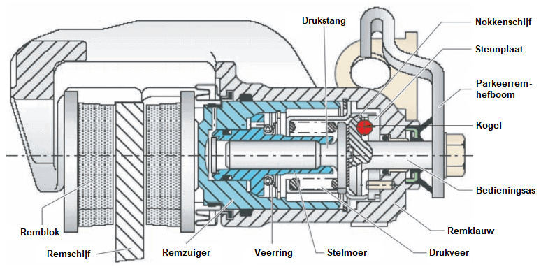
The adjusting nut and compression spring are responsible for compensating for brake pad wear. As the pads wear, the brake linings become thinner and the adjusting nut, acting as a “self-adjusting mechanism”, compensates for this play. When replacing the brake pads, the brake piston must therefore be wound back with special reset tools.
Combination of disc brake and drum brake:
In the paragraphs above, two different types of brake systems were described: the drum brake and the disc brake. In these versions, the service brake (which is operated hydraulically with the foot brake pedal) is combined with a parking brake mechanism.
A number of car manufacturers (including BMW and Opel) combine these brake systems on the rear axle. The brake disc serves as the service brake. The inner side of the brake disc serves as a brake drum for the parking brake. In the image this is clearly visible at the brake shoes. The brake cable operates the drum brake mechanism in order to slow down or lock the brake disc.
An alternative operating mechanism can also be seen. The driver operates the parking brake by pressing the parking brake pedal. This pedal is located at the far left next to the A-pillar.
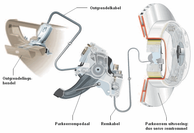
When the parking brake pedal is operated, a locking mechanism keeps the pedal depressed. Pressing the pedal harder causes it to move further down with more “clicks” and locks the parking brake more firmly.
To release the parking brake, the driver must pull the release lever. The lever is connected by the release cable to the mechanism behind the parking brake pedal. The parking brake will release fully at once and the pedal will spring back up to its uppermost position.
A similar mechanism can also be designed without a release lever. Among others, Toyota and vehicles from American manufacturers are equipped with a parking brake pedal with automatic release. With the parking brake engaged, the driver can unlock the mechanism again by pressing the pedal once more.
Electromechanical parking brake with electric motor on the brake caliper:
Vehicles can be equipped with an electromechanical parking brake. The driver can operate the electric motor on the rear brake calipers with a button on the dashboard. In addition, the vehicle can also control the parking brake mechanism when stationary on a hill. This function is called “hill hold”. The ECU operates the parking brake automatically when stopping and pulling away, so that the vehicle does not roll away. The driver can take his or her foot off the brake pedal.
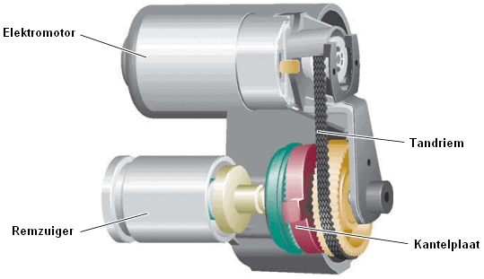
The rear brake calipers are equipped with an electromechanical mechanism that transfers the rotation of the electric motor to the brake piston.
The electric motor drives, by means of a toothed belt drive, the gear that is connected to a tilting plate. A spindle is attached to the tilting plate. The spindle is in fact a worm gear that can turn left or right; this depends on the direction in which the electric motor rotates. A large spindle nut is screwed onto the spindle; the spindle nut presses against the inside of the brake piston. Rotating the spindle causes the spindle nut to move inwards or outwards.
The images below show the electric parking brake at rest (left) and applied (right). The spindle is rotated, causing the spindle nut to push the brake piston against the brake pad. Because a floating caliper is used, both brake pads are pushed against the brake disc. In this situation, the brake is locked.
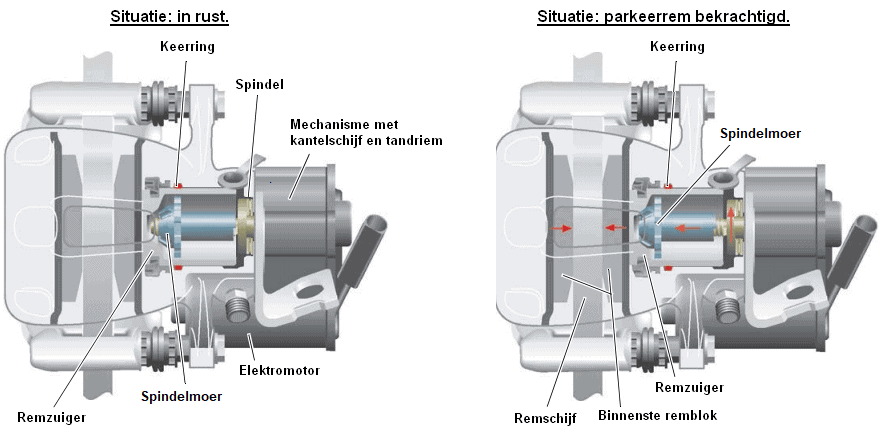
As soon as the parking brake is released, the electric motor drives the spindle via the mechanism to turn the spindle nut back inwards. The spindle nut does not pull the brake piston inwards; these parts are not connected to each other. The deformed seal pulls the brake piston back into its rest position.
In most cases, the parking brake is operated manually by pressing a button on the dashboard, or automatically when the ignition is switched off. The diagram below shows the electrical components of the VW Passat 3C.
The control unit for the parking brake (J540) receives a signal via the parking brake switch (E538) when it is operated by the driver. The power supply wire at the bottom of the internal switch (red) is then connected to the signal terminal of the control unit (green wire). As soon as the ECU detects a supply voltage at this terminal, it knows that the switch has been operated.
The control unit supplies the electric motors of the brake calipers with voltage. In the diagram, these wires are shown in blue and brown. The polarity can be reversed to make the motors rotate in the opposite direction.
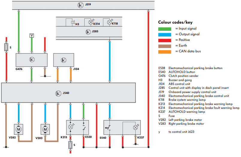
In addition to the signal from the parking brake switch, the parking brake control unit (J540) also receives information from other components:
- ABS computer (J104) to transmit the driving speed. The parking brake cannot, or can only to a limited extent, be operated while driving. The parking brake can also be helpful in an emergency stop and for the auto-hold function.
- Clutch position sensor (G476): the driver must operate the clutch pedal to release the parking brake.
- Auto-hold switch (E540): if the vehicle is equipped with auto-hold, the parking brake is automatically engaged when stationary on a hill. For this function, among other things, the signals from the ABS computer and the tilt angle detection are used.
The parking brake control unit provides the instrument cluster (J285) with information to operate the warning / fault indicator lamp and the buzzer.
Electromechanical parking brake with brake cables to the electric motor:
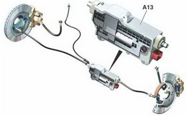
In another version of the electromechanical parking brake, there are no electric motors mounted on the brake calipers, but a single one centrally on the body, at the level of the rear axle.
The parking brake actuator is connected to the brake calipers by brake cables. In this respect, the system therefore has similarities with a manually operated parking brake.
The driver operates this actuator by pressing the button on the dashboard. The parking brake control unit switches on the electric motor to pull the handbrake cables tight or to release them.
When parking on a slope, an automatic control system actuates the actuator so that the vehicle cannot roll away.
Related pages: