Introduction to drum brakes:
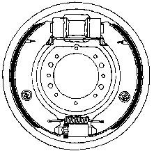
Drum brakes mainly consist of a brake drum and a backing plate, on which the brake shoes and wheel cylinders are mounted. When the brake pedal is pressed, the pistons of the wheel cylinders are pushed outward. These pistons push the brake shoes against the brake drum. After releasing the brake pedal, the return springs ensure that the brake shoes return to their rest position.
This page will be updated soon!
Different types of drum brakes:
Simplex
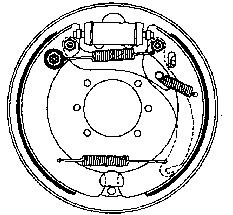
In the simplex design, both brake shoes are pushed outward by a single wheel cylinder with two pistons. There is a pivot point between the lower parts of the brake shoes.
Duplex
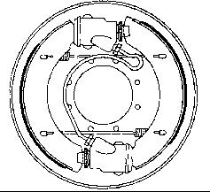
In the duplex system, two wheel cylinders are used, each with a single piston. Each brake shoe is pressed by its own wheel cylinder. When driving forward, both brake shoes have a self-energizing effect, which results in a higher braking force than with simplex brakes. When reversing, there is no self-energizing effect in either brake shoe. There is therefore a large difference in braking force between driving forward and reversing.
Duplex-duo
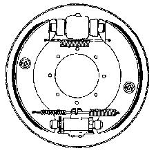
In the duoduplex system, two wheel cylinders are also used, but they are double-acting as in simplex brakes. This produces the same braking force when braking both forwards and in reverse.
Servo
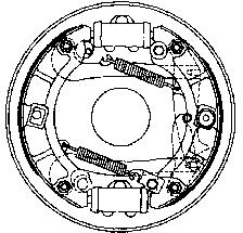
Servo brakes are equipped with a single double wheel cylinder (at the top) with the adjustment mechanism at the bottom. The servo system enables particularly powerful braking. Due to the self-energizing effect, the primary shoe presses on the secondary shoe via the thrust pin that can move to the right. This also gives the secondary shoe a self-energizing effect. When braking in reverse, only the right-hand brake shoe is self-energizing.
Duoservo
The duo-servo brake is equipped with a single double wheel cylinder. The difference compared to the servo brake is that the thrust pin can now move both to the right and to the left. As a result, both brake shoes are self-energizing when braking while driving forwards as well as when reversing.
Adjusting the brake shoes:
The brake shoes must be positioned as close as possible to the brake drum. If this is not the case, the brake pedal will have to be pressed further before the shoes contact the drum.
- Manual adjustment:
To compensate for wear, it is necessary to adjust the brake shoes according to the prescribed maintenance schedule. How and where this must be done depends on the brake design; for example, with small toothed wheels or a pin with a conical end. Instead of toothed wheels, eccentrics can also be used to adjust the brake shoes. Adjusting the brake shoes is usually done at the back of the backing plate. - Automatic adjustment:
There are also drum brakes with an automatic adjustment mechanism. A special toothed rod is clamped by a spring-loaded carrier. The head of the rod is mounted in an anchoring point on the backing plate. When braking, as the shoes move outward, the carrier pulls the rod along.
Measuring wear of the brake drum:
The internal diameter of the brake drum increases as it wears. In addition to the linings of the brake shoes, the diameter of the brake drum must also be checked for wear. The specifications for the relevant vehicle are listed in the manufacturer’s data. When the measured value is equal to or greater than the manufacturer’s specified limit, the brake drums must be replaced.
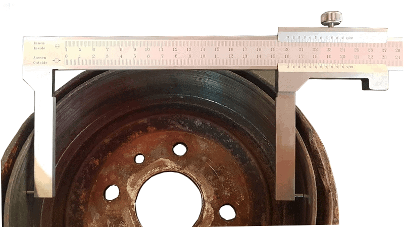
In the image below you can see a special caliper for brake drums. Distance pins can be seen on the outer sides of the measuring jaws. These distance pins must be placed against the deepest point of the brake drum. Therefore, slide the caliper back and forth several times to find the deepest point. The largest distance indicated by the caliper is the determining value.
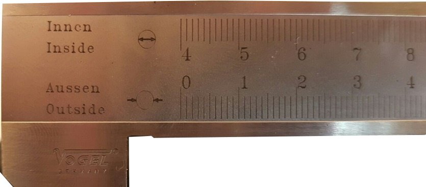
The next two images are an enlargement of the caliper shown above. Two scales can be seen on the caliper. The upper scale (Innen / Inside) shows the internal diameter. This is the one we read, because we are measuring the internal diameter of the brake drum. The lower scale is for the external diameter (Aussen / Outside). This is also shown in the accompanying drawing.
The upper scale starts at 4 cm (40 mm) because the measuring jaws, including the distance pins, are 4 cm thick in total. Because the internal diameter of the brake drum has been measured, we read the upper scale.
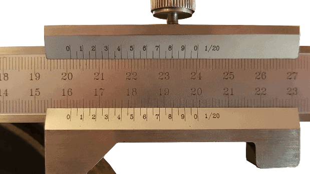
The measured value can be read in the figure.
First, you must check where the 0 of the vernier is located. It is just past 20.1 cm (201 mm). This means that there will be another digit after the decimal point. Which digit that is depends on which line of the vernier coincides with a line on the ruler. In this case, the 2 on the vernier coincides. This means that the digit after the decimal point is a 2, so the measured value is 20.12 cm (i.e. 201.2 mm).
In the manufacturer’s data for the car on which this measurement was taken, a minimum size of 201 mm is specified. The measured value of the brake drum is higher than the wear limit, so the brake drum will have to be replaced.
Related page: