Fuel supply and return system:
The fuel supply system ensures that the fuel is transferred from the tank to the engine. The electric fuel pump pumps the fuel from the tank and transfers it via the feed line and through the fuel filter to the fuel gallery (also called fuel rail).
Fuel pressure is then present at the inlet of the injectors. When an injector is actuated by the ECU, the fuel will be injected into the cylinder. The pressure regulator prevents the rail pressure from becoming too high. When the rail pressure rises too far, the pressure regulator ensures that the fuel flows back to the fuel tank via the return line.
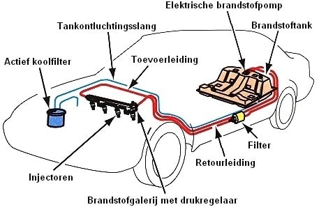
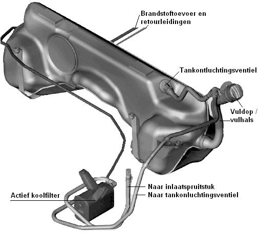
With a falling fuel level, more air must enter the fuel tank; otherwise a vacuum, or negative pressure, will occur. The opposite also applies; with a rising tank level, such as when refuelling, the air must escape from the tank. The vapours released in the process must not be released into the atmosphere. That is why an activated charcoal canister is used to provide ventilation of the fuel tank. Via a tank vent hose, the tank is supplied with or relieved of air by means of the tank vent valve.
The following paragraphs describe the components of the fuel system of the petrol engine.
Fuel tank:
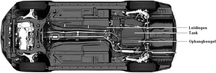
The function of the fuel tank is to store fuel. The fuel tank is almost always mounted underneath the rear of the car, at the level of the rear wheels, under the rear seat. The tank is attached to the body with mounting brackets. The fuel tank is never located within the crumple zone of the vehicle. Due to its low weight and the possibility of producing all kinds of complex shapes, the fuel tank is almost always made of plastic. By shaping the tank in such a way that every available space is used, the largest possible capacity is created.
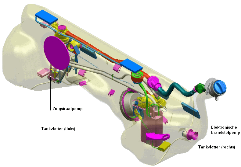
The fuel tank in the image below is called a “saddle tank” because of its shape. This tank is fitted in a rear‑wheel‑drive car. In the raised section in the middle, space has been created for the propeller shaft. In a front‑wheel‑drive car, the bottom of the tank will be flatter. The fuel pump in the tank provides the fuel supply to the engine. A so‑called suction jet pump is also used in a saddle tank to transfer the fuel to the other half of the tank. The operation of these fuel pumps is described further down this page.
There are always 2 fuel lines running from the tank to the engine, namely a supply line and a return line. As the name suggests, the supply line carries the fuel from the fuel pump to the engine. The return line carries the excess fuel back to the tank. There is also always a tank vent valve on the tank, which is connected to the activated charcoal canister by a vent hose.
Activated charcoal canister:
The activated charcoal canister is shown in the image above. The activated charcoal canister ensures that HC emissions (fuel vapours) do not end up in the atmosphere. This canister draws the fuel vapours from the tank and filters them through the special absorptive carbon material. After the fuel vapours have been filtered, they are discharged to the outside air or to the intake system of the engine. The vapours are mixed with the intake air and then burned. In this way, the fuel vapours are discharged as cleanly as possible.
The activated charcoal canister can be mounted near the fuel tank, but sometimes it is also located under the bonnet. In some cars where it is mounted under the bonnet, a noticeable ticking sound can sometimes be heard that often disappears and then returns. That is the moment when the activated charcoal canister is operating.
Fuel pump:
In classic cars we often still find a mechanical fuel pump that is driven by the camshaft. The mechanical fuel pump has been replaced by an electric lift pump: this provides the required pressure for an indirectly injected petrol engine. Today, (almost) all car manufacturers use high‑pressure injection; the fuel is injected directly into the combustion chamber at high pressure. This high pressure is achieved thanks to the high‑pressure fuel pump.
The operation and application of these fuel pumps are explained on the page Fuel pump of the petrol engine.
Suction jet pump:
As described in the second paragraph, the saddle tank consists of two parts. The fuel levels on both sides must constantly be kept the same. The suction jet pump transfers the fuel from one half of the tank to the other. The fuel then ends up in the half of the tank where the electric fuel pump is located. The electric fuel pump transfers the fuel to the engine.
There is a negative pressure in the suction jet pump. By allowing fuel to flow through a narrowing, the flow velocity of the liquid increases (see the image below). This creates a negative pressure after the narrowing, with which fuel can be drawn in. A suction jet pump operates according to the same venturi principle as a carburettor, only the venturi effect is created not by an air flow, but by a liquid flow.

Float:
A float in the fuel tank has the task of measuring the fuel level and sending this signal to the instrument panel. The tank contents can be read there. If the car is equipped with an on‑board computer, the estimated range is calculated based on the driving style. The float has a piece of polystyrene foam. This foam block continues to float on the fuel. When the fuel level drops, the foam block also drops. Due to this mechanical movement, a needle moves over a potentiometer (a variable resistor). Due to a high or a low resistance, a low or a high current is produced. Based on this current strength, the needle on the instrument panel moves from low to high.