Topics:
- Introduction
- Materials and specifications of different types of batteries
- Lead-acid battery
- Nickel-cadmium (Ni-Cd)
- Nickel-metal hydride (Ni-MH)
- Lithium-ion (li-ion)
– Construction of a battery pack: series and parallel connections
– Voltage range of a lithium-ion cell - Super capacitor (supercap)
- Battery cell balancing
Introduction:
The hybrid or fully electric car has larger, heavier batteries than cars with only a combustion engine. In hybrid cars, high voltages are used which can be life-threatening during repairs when handled by unqualified people. For example:
- A starter motor in operation uses around 1.2 kW (1200 watts)
- A hybrid car driving fully on electricity uses around 60 kW (60,000 watts)
Work on hybrid cars may only be carried out by people who have completed special training. There is a 12-volt on-board network to power accessories (such as the radio, etc.) with its own small battery, and there is a high-voltage on-board network which (depending on the brand) operates at 400 volts. The 400 V voltage is converted to 12 V by a special DC/DC converter, which charges the respective battery.
High demands are placed on hybrid drive batteries. They must have a very large storage capacity. Large amounts of energy are stored, and very high voltages are taken when supporting the combustion engine (hybrid), or when providing energy for the complete drive (BEV).
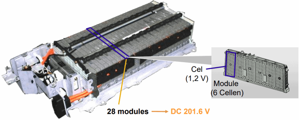
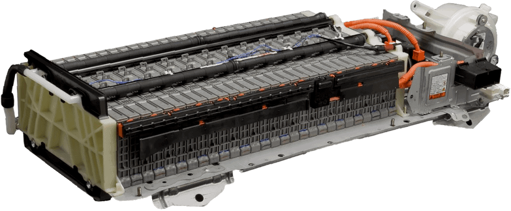
The image below shows a battery pack from a Toyota Prius. This Nickel Metal Hydride (NiMH) battery contains 28 modules, each consisting of 6 cells. Each cell has a voltage of 1.2 volts. The total voltage of this battery pack is 201.6 volts.
Materials and specifications of different types of batteries:
When developing the electric powertrain, a choice is made between different types of batteries. Their properties, performance, construction possibilities and costs play a major role in this. The most commonly used battery types in hybrid and fully electric vehicles are Ni-MH (nickel-metal hydride) and li-ion (lithium-ion) batteries.
In addition to Ni-MH and li-ion types, there is ongoing development of electrolytic capacitors, which we categorize under the term “super capacitor” or “supercaps”.
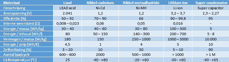
The table shows the materials of the different batteries with their specifications.
Lead-acid battery:
The table also mentions the lead-acid battery (gel and AGM versions are not taken into account). Because the lead-acid battery has the longest service life at a maximum discharge of 20%, suffers from sulfation as it ages, and has a low energy density and content, it is not suitable for use in electric vehicles. However, we do find the lead-acid battery used as an auxiliary battery; the low-voltage consumers such as lighting, comfort systems (body) and the infotainment system operate at a voltage of around 14 volts.

Nickel-cadmium (Ni-Cd):
In the past, Ni-Cd batteries suffered from a memory effect and were therefore unsuitable for use in electric drivetrains: continuous partial charging and discharging takes place there. Modern Ni-Cd batteries are now almost unaffected by the memory effect. The biggest disadvantage of this type of battery is the presence of the toxic substance cadmium. This makes the Ni-Cd battery extremely harmful to the environment. The use of this battery is therefore legally prohibited.
Nickel-metal hydride (Ni-MH):
The Ni-MH battery can be charged faster than a lead-acid battery. During charging, both heat and gas are generated, which must be removed. The batteries are equipped with a cooling system and a vent valve. Thanks to its long service life and high energy and power density, the Ni-MH battery is suitable for use in electric vehicles. However, this type of battery is sensitive to overcharging, excessive discharging, high temperatures and rapid temperature changes.
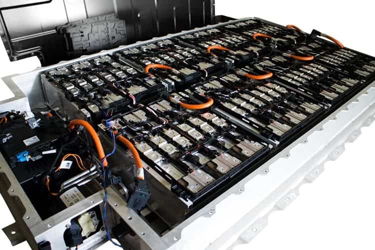
The image below shows the Ni-MH battery pack of a Toyota Prius. This battery pack is located in the trunk, behind the rear seat backrest. When the temperature sensors register a high temperature, the cooling fan is activated (visible on the right side of the photo by the white housing). The fan draws air from the interior and blows it through the air channels in the battery pack to cool the cells.
Lithium-ion (li-ion):
Because of the high energy and power density of the lithium-ion battery (compared to Ni-MH), a li-ion battery pack is usually used in plug-in hybrids and fully electric vehicles. The li-ion battery performs reasonably well at low temperatures (although power does decrease, so many EV batteries have a heating system) and has a long service life. It is expected that in the coming years, thanks to further development of battery management among other things, technologies will improve so that both range and service life will increase even further.
The next image shows the (li-ion) battery pack of a BMW i3. The cover has been unscrewed and is placed behind it. When installed, the cover seals the pack airtight.
The battery pack of the i3 is mounted underneath the vehicle. The floor space between the front and rear axles is used as efficiently as possible to provide as much room as possible for the battery pack.
In the image we see the eight separate blocks, each with twelve cells. Each block has a capacity of 2.6 kWh, making a total of 22 kWh. For comparison: the current generation i3 (as of 2020) has a battery with a capacity of 94 Ah and an energy content of 22 kWh. The size of the battery pack has remained the same since its introduction in 2013, but its performance (and therefore its range) has improved significantly.
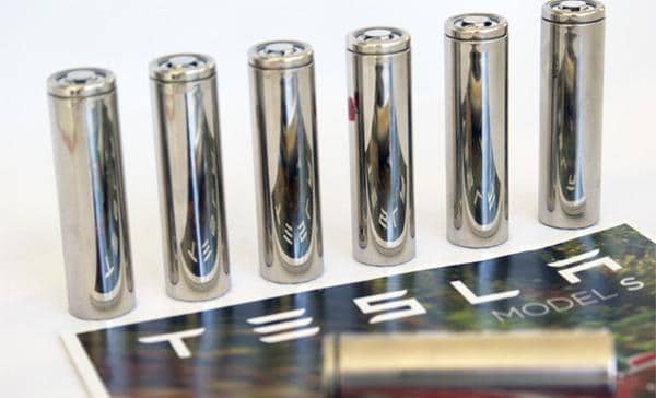
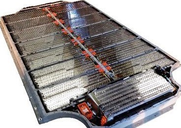
Since 2013, Tesla has used in its models (Model S and Model X) small battery cells that are slightly larger than the standard AA batteries we know from a TV remote. The battery cells (18650 from Panasonic) are 65 mm long and have a diameter of 18 mm. The most extensive battery packs contain no fewer than 7,104 of these cells.
In the images below we see the loose battery cells on the left and on the right a battery pack housing the 7,104 cells.
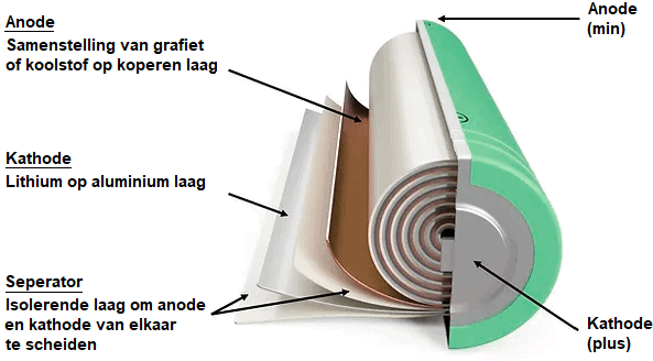
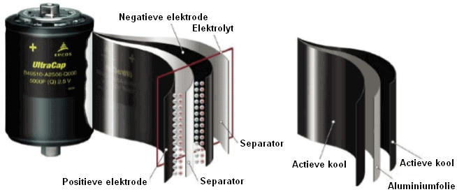
The lithium-ion battery is made up of four main components:
- the cathode (+) consisting of a lithium alloy
- the anode (-) consisting of graphite or carbon
- the porous separator
- the electrolyte
During discharge, the lithium ions move through the electrolyte from the anode (-) to the cathode (+), to the consumer and back again to the anode. When charging, the ions move in the opposite direction, from the cathode (+) to the anode (-).
The electrolyte contains lithium salts to transport the ions. The separator ensures that the lithium ions can pass through, while the anode and cathode remain separated from each other.
Construction of a battery pack: series and parallel connections:
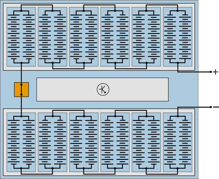
The battery cells are housed in modules that are connected in series. The following schematic representation below shows a battery pack that strongly resembles those of a Volkswagen E-UP! and Renault Zoë. Only the number of cells differs: the E-UP! battery pack has 204 cells and that of the Renault Zoë has 192.
In this example, the battery pack consists of two packs of six modules. Each module contains two parallel-connected groups of 10 series-connected cells.
- Series connection: the battery voltage increases. With a cell voltage (li-ion) of 3.2 volts, one battery module supplies (3.2 * 10) = 32 volts.
The disadvantage of a series connection is that in the case of a bad cell, the capacity of the entire series connection becomes lower. - Parallel connection: the voltage remains the same, but the current and capacity increase. A bad cell does not affect the cells in the circuit that is connected in parallel with it.
Manufacturers can therefore choose to apply multiple parallel connections per module. In the modules of the Volkswagen E-Golf, therefore, not two (as in this example), but three groups of cells are connected in parallel.
The images below show the battery modules and specifications of a Volkswagen ID.4, where again the series and parallel connections can be seen in two different configurations. Both packs contain 24 cells, but the choice between the number of series and parallel connections determines the nominal voltage and the capacity per module.
| 62 kWh | 82 kWh | |
|---|---|---|
| Materiaal | Lithium-ion | Lithium-ion |
| Celtype | Prismatic | Prismatic |
| Fabrikant | LG | LG |
| Gewicht per module | 30 kg | 30 kg |
| Capaciteit per batterijcel | 78 Ah | 78 Ah |
| Aantal cellen | 24 | 24 |
| Aantal modules in pakket | 8 | 12 |
| Schakeling in module | 12 serie, 2 parallel | 8 serie, 3 parallel |
| Capaciteit per module | (2 * 78) = 156 Ah | (3 * 78) = 234 Ah |
| Nominale spannig per cel | 3,7 volt | 3,7 volt |
| Nominale spannig per module | 44,4 volt | 29,6 volt |
| Energie per module | (44,4 * 156) = 6,93 kWh | (29,6 * 234) = 6,93 kWh |
| Energie totale batterijpakket | (8 * 6,93) = 55,4 kWh | (12 * 6,93) = 83,2 kWh |
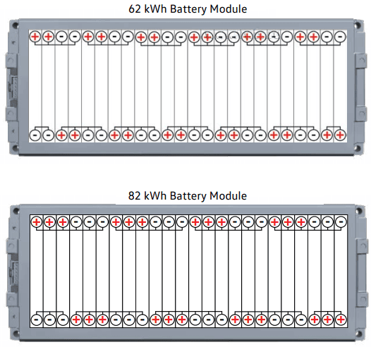
The calculated energy of the total battery pack differs from the energy quoted for the packs. For example, for the 62 kWh pack it is calculated that it provides about 55.4 kWh, while for the 82 kWh pack about 83.2 kWh is calculated. So there is a discrepancy.
Possible causes of this are the manufacturer’s marketing designation, rounding of values, the use of a different nominal voltage per cell (for example a higher average voltage within the operating range), and the discharge characteristics of a cell. A pack with fewer parallel-connected cells has a lower capacity per module and discharges according to a different discharge curve.
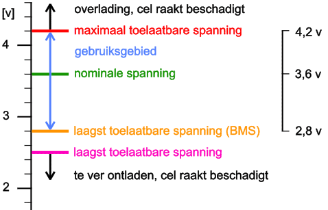
Voltage range of a lithium-ion cell:
Lithium-ion cells have a service life of approximately 2,000 discharge and charge cycles before their capacity is reduced to about 80% of their initial charge capacity.
The voltages of a li-ion cell are as follows:
- nominal voltage: 3.6 volts;
- discharge limit: 2.5 volts;
- maximum charging voltage: 4.2 volts.
Most Battery Management Systems (BMS) use a lower limit of 2.8 volts. When the cell is discharged further than 2.5 volts, the cell becomes damaged. The service life of the cell is shortened. Overcharging the li-ion cell also reduces its service life and is also dangerous. Overcharging the cell can make it flammable. The temperature of the cells also affects service life: at temperatures below 0°C, the cells may no longer be charged. A heating function provides a solution in this case.
Super capacitor (supercap):
In the previous sections, different battery types were mentioned, each with their applications, advantages and disadvantages. One disadvantage that everyone with such a battery has to deal with is the charging time. Charging a battery pack can take several hours. Fast charging is an option, but it is accompanied by more heat and possibly also faster ageing (and damage) of the battery pack.
Currently a lot of research and development is taking place into super capacitors. We also call these “super caps” or “ultracapacitors”. The use of supercaps could offer a solution here:
- Charging is very fast;
- They can deliver energy very quickly (discharge), so a considerable power increase is possible;
- More durable than a li-ion battery thanks to an unlimited number of charge cycles (at least 1 million) because no electrochemical reactions take place;
- Partly due to the previous point, a supercap may be fully discharged without any harmful effects on service life.
Supercaps are capacitors with a capacitance and energy density that are thousands of times higher than standard electrolytic capacitors. The capacitance is increased by using a special electrolyte (insulating material) that contains ions and therefore has a very high dielectric constant between the plates. A separator (a thin film) is soaked in a solvent with ions and placed between the plates. The plates are usually made of carbon.
The capacitance of the capacitor shown is 5000 F.
Supercaps can be combined with a li-ion HV battery; during brief acceleration, the energy from the capacitors can be used instead of energy from the HV battery. During regenerative braking, the capacitors recharge fully again within a fraction of a second. Future developments may also make it possible to replace the li-ion battery with a supercap pack. Unfortunately, with current technology the capacity and therefore the power density are too low compared to a lithium-ion battery. Scientists are looking for ways to increase capacity and power density.
Battery cell balancing:
By means of passive and active battery cell balancing (English: cell balancing), each cell is monitored by the ECU to maintain a healthy battery status. This extends the service life of the cells by preventing deep discharge or overcharging. Lithium-ion cells in particular must remain within strict limits. The voltage of the cells is proportional to the state of charge. The charge of the cells must be kept as much as possible in balance with each other. With cell balancing it is possible to control the state of charge with an accuracy of 1 mV (0.001 volt).
- Passive balancing ensures an equilibrium in the state of charge of all battery cells by partially discharging the cells with too high a state of charge (we will come back to this later in the paragraph);
- Active balancing is a more complex balancing technique that can control the cells individually during charging and discharging. The charging time with active balancing is shorter than with passive balancing.
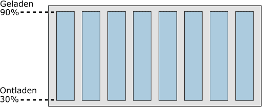
In the following image we see a battery module with eight cells.
The eight cells are charged to 90%. The service life of a cell decreases if it is continually charged to 100%. Conversely, the service life also decreases if the battery is discharged further than 30: at a state of charge of <30% the cell is deeply discharged.
The state of charge of the cells will therefore always be between 30% and 90%. This is monitored by the electronics, but is not visible to the driver of the vehicle.
The digital display in the instrument panel indicates 0% or 100% when 30% or 90% is reached.
Due to aging, a number of cells may become weaker than the others. This has a major influence on the state of charge of the battery module. In the next two images we can see the state of charge when two cells have a lower capacity due to aging. The battery cells in these situations are not balanced.
- Discharges faster due to bad cells: the two middle cells have discharged faster due to their lower capacity. To prevent deep discharge, the other six cells in the module can no longer supply energy and therefore can no longer be used;
- Does not fully charge due to bad cells: due to the low capacity of the middle two cells, they charge faster. Because they reach 90% faster than the other six cells, charging cannot continue.
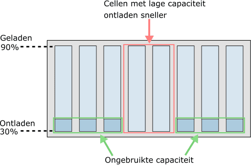
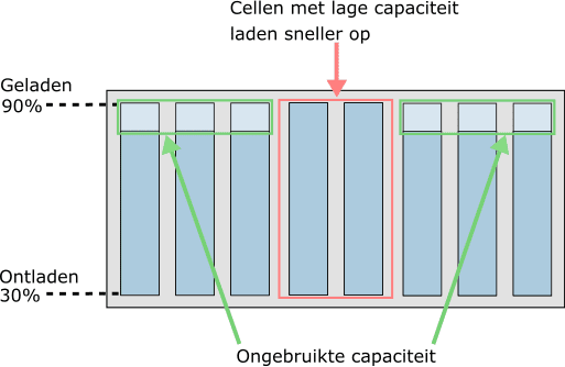
It is clear that cells with a lower capacity are the limiting factor both during discharging (while driving) and during charging. To make optimal use of the full capacity of the battery pack and to benefit a long service life.
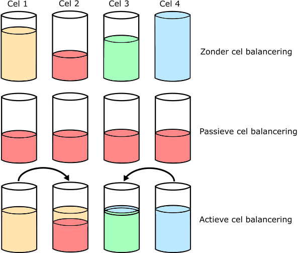
There are two methods for battery balancing: passive and active.
- Without balancing: four cells all have a different state of charge. Cell 2 is almost empty and cell 4 is fully charged;
- Passive: the cells with the highest capacity are discharged until the state of charge of the weakest cell (cell 2 in the example) is reached. The discharge of cells 1, 3 and 4 is a loss.
In the example we see that the cups are discharged until they have reached the state of charge of cell 2; - Active: the energy from the full cells is used to fill the empty cells. There is now no loss, but the transfer of energy from one cell to another.
Below, the operating principle of passive and active cell balancing is explained.
Passive cell balancing:
In the example we see four series-connected battery cells with a switchable resistor (R) connected in parallel across them. In this example the resistor is connected to ground with the little switch. In reality this is a transistor or FET.
In the example we see that cell 3 is charged to 100%. From the previous paragraphs we know that this cell charges faster because it is weaker than the other three. Because the state of charge of cell 3 is 100%, the other three cells are no longer charged.
The resistor that is connected in parallel across cell 3 is brought into the circuit by the switch. Cell 3 discharges because the resistor absorbs voltage as soon as current flows through it. The discharge continues until the cell is at the level of the other cells; in this case 90%.
When all four cells in this module have the same state of charge, they can be charged further.
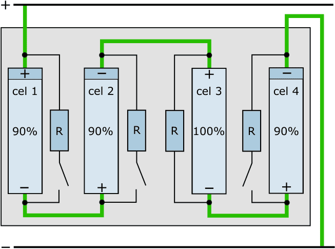
With passive cell balancing, energy is lost: the voltage absorbed by the resistors connected in parallel has in fact been lost. Nevertheless, to this day many manufacturers use this method of balancing.
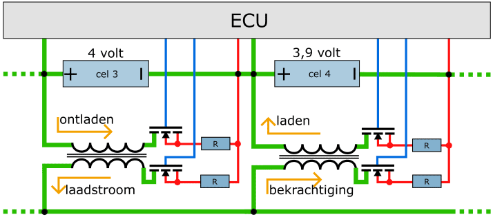
Active cell balancing:
Active cell balancing is of course much more efficient. In this case, the energy from the overcharged cell is used to charge the empty cell. An example of active cell balancing is shown below.
In the example we see two series-connected cells (3 and 4) with their voltages above them (4 and 3.9 volts respectively). Cell 3 is discharged by means of the transformer. The FET on the primary side makes discharging possible. The primary winding in the transformer is thereby charged. The FET on the secondary side switches the secondary winding of the transformer on. The resulting charging current is used for the excitation of the transformer under another cell. The transformer under cell 4 is likewise switched on and off by FETs.