Introduction:
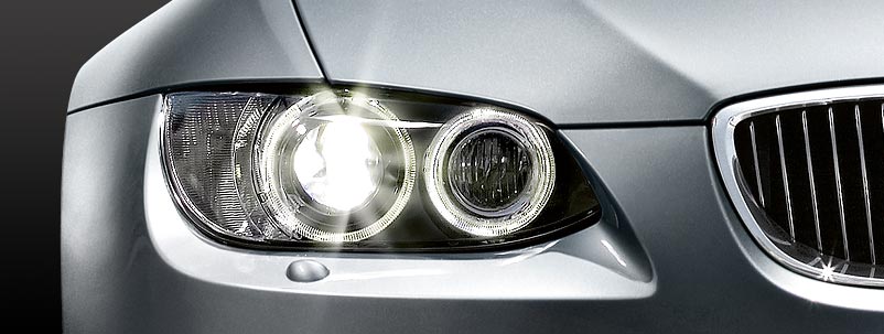
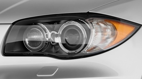
The headlamps provide illumination at the front of the car. Some cars have all lighting in one housing (as with the car in the image below) and others have multiple units. The mandatory front lighting consists of: side lights, low beam, high beam, indicators and possibly fog lamps and daytime running lights. For the lamps you can choose between a glow bulb, halogen bulb, xenon and / or LED.
Colours:
The side lights must be yellow or white when lit. As standard, halogen bulbs are used. Bulbs with a blue coating are intended to emit as white as possible (e.g. with xenon). Low beam and high beam must be yellow or white. Xenon bulbs often appear blue/purplish in colour, but on the headlamp aiming device the light pattern is usually still simply white. Other colours are not permitted.
Front indicators may be orange, yellow or white. Fog lamps are subject to the same requirements as low and high beam; they must be yellow or white.
Daytime running lights may only be white. In America the “daytime running lights” are often orange and remain on constantly with the main lighting switched off. In the Netherlands this is prohibited and the orange bulbs must be replaced with white ones. If that is not possible, they must be disabled. This often causes another problem when the daytime running lights and indicators are combined; then the only solution is to fit white bulbs. White indicators are allowed after all.
Xenon bulbs are often combined with headlamp washers in the headlamp housing or in the front bumper. This is to prevent stray light caused by, for example, dirt and insects on the headlamp lens.
H4 and H7 bulbs:
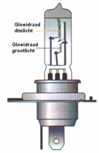
The most commonly used types of bulbs are H4 and H7. At the bottom left an H4 bulb is shown. This bulb has two filaments behind one another; one for low beam and one for high beam. When the low beam is switched on and the driver flashes (or switches on the high beam) the low beam will briefly switch off.
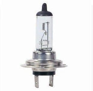
At the bottom right an H7 bulb is shown. This bulb has only one filament; this is only for low beam. A separate bulb is therefore needed for the high beam.
The H4 bulb is much thicker than the H7 bulb, so they cannot accidentally be swapped in the headlamp housings. The H4 bulb also has three connections on the plug and the H7 bulb has two.
Reflectors:
Low beam reflector:
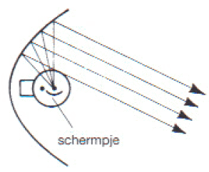
The low beam bulb shines upwards, onto the top of the parabolic reflector. This reflector reflects the light back at a certain angle. These light rays must of course be directed downwards. Some people mount the bulb the wrong way round in the headlamp (with force, because it is actually not possible). The light rays then go upwards and dazzle all oncoming traffic.
High beam reflector:
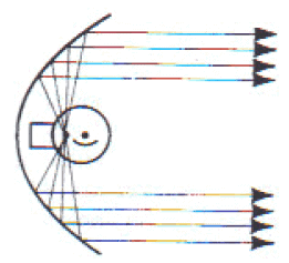
The high beam bulb radiates in all directions, upwards and downwards, to the left and to the right. The reflector reflects the light rays straight ahead, which produces a large light bundle. The light output is now at its maximum, but very annoying for oncoming traffic which is dazzled.
Low beam light pattern:
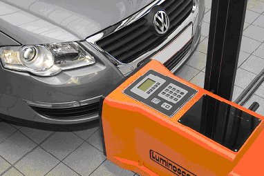
The light pattern of the car is measured and adjusted if necessary during a major service and the periodic inspection (APK). An aiming device is placed in front of the headlamp, containing a small screen that measures the light incidence. Based on the light pattern in the aiming device, the headlamp can be adjusted by turning the adjusting mechanisms in the headlamp. The fog lamps can also be adjusted in this way, but this is usually only done after removing/refitting or replacing the fog lamp units.
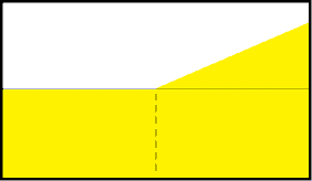
Below four different light patterns are shown (with light pattern 1 as an example of a high or low setting). The other three light patterns are commonly seen in practice. When a headlamp fails the APK due to a poor light pattern caused by weathered headlamp lenses or reflectors, many people do not know how the inspector determines this. These images make that much clearer. A borderline case is also shown, which can still just pass the inspection.
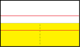
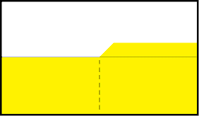
Light pattern 1:
This only shows the horizontal line. The black dotted line indicates how far the light (yellow area) may extend. This is often between 1.0% and 1.5% on cars without xenon and about 2% on cars with xenon. The upper red line shows where the light pattern would be if the headlamps were adjusted at 0% (too high). The lower red line indicates a light pattern that is too low (e.g. 3%). It may also be that in this case the adjuster motor is set too far down, which can be adjusted in the interior. This must always be set to 0 before adjustment.
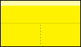
Light pattern 2:
A perfect light pattern. A good height, with on the right-hand side the light arc that shines towards the verge. This is always the case with cars that drive on the right-hand side of the road. With British cars this light arc is directed to the left. That is why there are often stickers on the headlamps of British cars when they go to another country. This is purely to block this light arc in order to prevent dazzling oncoming traffic.
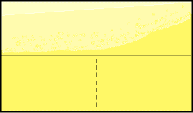
Light pattern 3:
With cars that have weathered headlamp lenses or weathered reflectors, the light pattern often looks like this. There is a lot of scattered light; there is a lot of light present above the cut-off line. Sometimes it is so bad that no cut-off line is visible anymore. The headlamp then essentially shines in all directions, while the light output (and therefore visibility) is also minimal. It is up to the inspector to determine whether it is a fail, or whether it is still acceptable.
If a horizontal cut-off line is still visible (as in this image) it may still just pass.
Light pattern 4:
If the bulb is mounted the wrong way round in the headlamp, the light does not shine downwards but upwards. That is clearly visible in this image. See the image on the right.
American headlamp:
American headlamps differ from European versions. They often contain an orange reflector or additional orange lighting, which the European version does not have. The indicators also burn constantly (if the indicators themselves do not burn, other orange lamps have been added to the car). The orange lamps switch on as soon as the ignition is turned on (just like daytime running lights). In the Netherlands this is not allowed. The orange lamps may only be used as indicators and may not burn constantly, not even if they are driven at only 50%. This leads to an APK failure and is a reason for a fine during a traffic check.
Another difference between the headlamps is the light pattern. The light pattern of an American headlamp runs horizontally on the right-hand side of the pattern, contrary to the European regulations. From the centre the light pattern rises slightly and then the line runs horizontally to the right. The headlamp now shines more straight ahead than into the verge. With imported cars this can sometimes cause problems. In principle this does not comply with European requirements, so the inspector could regard this as a fail. This also purely depends on how high the line on the right-hand side is compared to the left-hand side.
Headlamp height adjustment:
The headlamp height is adjustable so that it can be set lower when the vehicle is loaded. The tilt motor, also called the mirror adjustment motor or adjuster motor, ensures that the reflector in the headlamp tilts vertically around its axis.
The three systems for adjusting the headlamp height are:
- Static height adjustment. The driver operates the adjustment using a knob on the dashboard.
- Dynamic height adjustment. In this case the height adjustment responds to body movements.
- Semi-static height adjustment. The sensors on the control arms register the vehicle load. When the vehicle is loaded at the rear, for example, the rear of the vehicle drops and the headlamps shine upwards. The semi-static height adjustment then adjusts the headlamps downwards.
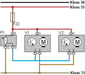
The diagram on the right-hand side shows the static headlamp height adjustment. The diagram is of the “waterfall” type, where the positive (terminal 30) is at the top and the ground (terminal 31) at the bottom. The circuit is protected by fuse F22. The potentiometer (P1) is the adjustment knob that can be turned by the driver. The potentiometer is a variable resistor and has a positive (pin 1), ground (pin 2) and a signal wire (3). The voltage on the signal wire depends on the position of the wiper of the potentiometer. The wiper is indicated as an arrow on the resistor. The voltage reaches adjustment motors 1 (V1) and 2 (V2) via the blue wire. The electronics of the adjustment motors (indicated by the transistor symbol) will adjust the motors to the desired position.
In the diagram, only a positive wire, ground wire and signal wire are shown for an adjustment motor.
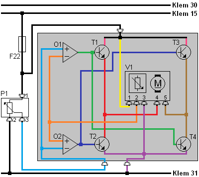
The control unit reads the position of the adjustment motor and then controls it to set it to the correct position. The diagram below shows what actually happens in the control unit. The diagram and the text relate to the left adjustment motor (V1).
The control unit contains two op-amps and four transistors, which in this case are configured as a differential amplifier. Depending on the voltage difference between the potentiometers in the dashboard and in the adjustment motor, the transistors are controlled by the op-amps. This voltage difference arises, for example, when the driver turns the adjustment wheel (P1) downwards. The wiper on the variable resistor takes a different position. As a result, more or less voltage will be lost as heat. The voltage on pin 3 of P1 will therefore become higher or lower. This voltage reaches the two op-amps (O1 and O2) via the blue wire. The op-amps measure the voltage difference between the two potentiometers (P1 and V1), i.e. between the blue and orange wires.
- At rest: When the voltage on the blue and orange wires is equal, the system is at rest.
- Adjustment wheel turned down: Transistors T1 and T4 are driven into conduction by op-amp O1 when the voltage on the blue wire is higher than on the orange wire. The adjustment motor receives its supply on pin 4 via the red wire (via T1) and ground on pin 5 via the brown wire (via T4). As a result, the adjustment motor turns clockwise until the voltage from its potentiometer reaches the same voltage as the potentiometer in the dashboard (P1). When there is no longer a voltage difference between the wires, the op-amp will no longer output a voltage.
- Adjustment wheel turned up: When the driver turns the adjustment wheel in the opposite direction, the voltage on the orange wire becomes higher than on the blue wire. Op-amp O2 now outputs a voltage. Transistors T2 and T3 are driven into conduction. The adjustment motor now turns counterclockwise, i.e. in the opposite direction, because the polarity has been reversed compared to the previous situation. The control stops again as soon as the op-amp no longer detects a voltage difference between the wipers of the potentiometers.
Measuring and connecting headlamp wiring:
The headlamp wiring harness can be damaged after a collision, incorrect installation causing the wiring to become pinched, or because the harness rubs against something. The wiring can be damaged or even break. To repair the wiring, in most cases the same color wires can be reconnected to each other. A technician must be able to determine which wire has which function by reading the wiring diagram and performing measurements. At that point, the wires on the vehicle side can be connected to the headlamp wiring. This knowledge and these skills are part of the practical exam for first technician.
In the electrical diagram below, a lighting system for the front of a vehicle is shown. On the right of the diagram the legend is shown. The diagram is of the “waterfall” type, with the positives at the top (terminal 30 and 15) and ground at the bottom (terminal 31). In the diagram several switches are shown that are connected to a control unit (A20). This ECU switches the indicator lights (E5 and E6) on, as well as the relays for the dipped-beam and main-beam lamps. The side/parking light is switched on and off directly by the light switch (S21). Furthermore, the headlamp adjustment motors (M01 and M02) are shown, which rotate up or down based on the signal from the adjustment wheel containing the potentiometer.
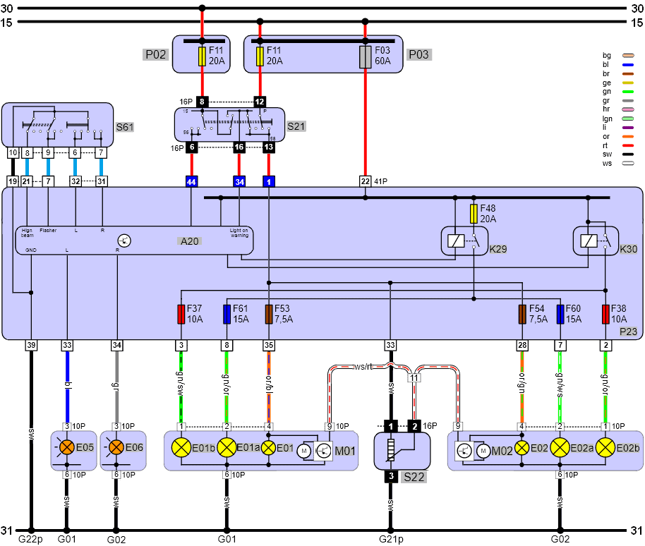
P02: fuse box for terminal 30;
P03: fuse box for terminal 15;
S61: steering column switch (indicator and main beam);
S21: Light switch (parking and main lighting)
A20: Control unit;
K29: Dipped-beam relay;
K30: Main-beam relay;
E05: Indicator L;
E06: Indicator R;
E01B: Main beam L;
E02B: Main beam R;
E01A: Dipped beam L;
E02A: Dipped beam R;
E01: Parking light L;
E02: Parking light R;
M01: Left headlamp height adjustment motor;
M02: Right headlamp height adjustment motor;
S22: Headlamp height adjustment wheel
G01: Ground point front left;
G02: Ground point front right;
G2*p: Interior ground point
As described above, a technician must be able to connect the headlamp wiring by reading the diagram and performing measurements. To clarify this, below is a step-by-step plan to connect the (cut) wires on the vehicle side (often one color, in this case red) to the colored loose wires of the headlamp.
Side light / parking light:
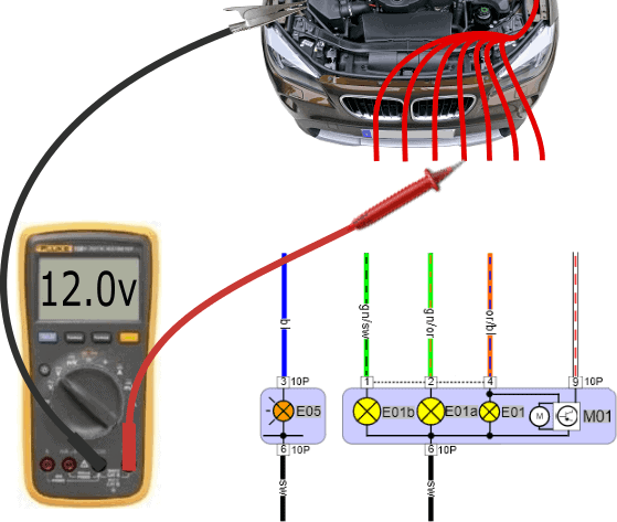
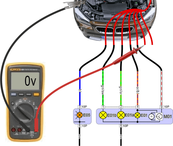
First, we check whether, with the lighting switched off, the voltage on all wires coming from the car relative to ground is 0 volts.
In the legend we saw that the code E01 is for the left parking light in the headlamp. Using the voltmeter, we will look for the positive wire of this lamp.
- Ground lead of the voltmeter: connect to a good ground point, preferably with a crocodile clip to a ground point intended for the battery charger;
- Positive lead: one of the six wires has changed from 0 volts to the system voltage (12 to 14 volts). We measure the red wires one by one and locate the relevant wire. To check, the side light can briefly be switched off and on to see whether the voltage switches between 0 and 12 volts.
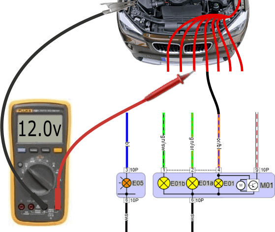
Dipped beam:
We connect the side light from the previous measurement to the or/bl (orange/blue) wire and switch on the dipped beam. Now the voltage on two wires is 12 volts: the side light (remains on) and the wire for the dipped beam. We locate this wire.
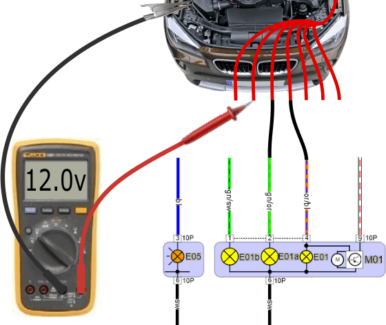
Main beam:
After the dipped-beam wire has been connected to the gn/or (green/orange) wire, we switch on the main beam. One of the remaining red wires has become 12 volts. We connect this wire to the gn/sw (green/black) wire of E01b (main beam).
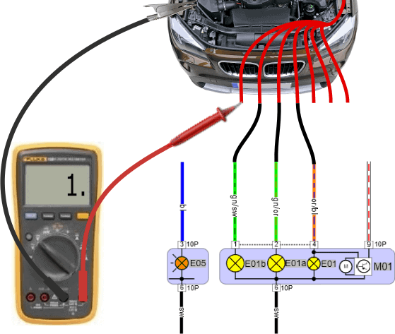
Indicator:
A voltmeter can be too slow to measure the alternating voltage between 0 volts (off) and 12 volts (on) when the indicator is switched on:
- The voltage reading on the display may jump around;
- “Infinite” or “overload” may appear in the display.
An oscilloscope could be used to check the square-wave voltage, but this is not really necessary. When switching the indicator on or off, we see a change in voltage on the display, which gives us enough information that we are measuring on the correct wire. We then connect this wire to the bl (blue) wire of E05 (indicator).
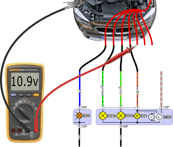
Height adjustment:
On one of the wires, after switching on the side light or dipped beam, a lower voltage will be measured than on the positive wires of the lamps. In this case we measure 10.9 volts. With a deviating voltage value we are almost always dealing with the signal wire for the headlamp adjustment motor.
In the interior (dashboard, steering column, instrument cluster) there is the adjustment wheel or digital button to move the headlamp adjustment motors up or down. In position 0 (headlamps at their uppermost position) the voltage is often high. When we turn the adjustment wheel to position 2 or 3, the voltage on the signal wire to the adjustment motor drops: this gives it the command to move downwards. In position 3 the voltage can drop to 6 or 7 volts.
We then connect the wire for the height adjustment to the ro/wi (red/white) wire. Unfortunately, the color coding is missing in the diagram.
Ground (1):
So far all positive wires have been connected, but without ground wire(s) the lamps and the adjustment motor still do not work. The voltage on the remaining wire has remained 0 volts during all measurements. To be sure that the wires on which you measure 0 volts are ground wires, we perform a resistance measurement. This measurement is shown below.
Ground (2):
The resistance on the red wires relative to the ground point on the body is 0.1 ohms in both cases. It may happen that the resistance value is slightly higher, e.g. 5 ohms. Now that we are sure that the last two red wires are connected to the body, we connect them to the black wires of the headlamp.
- Vehicles where the indicator is in a different unit or a different part of the headlamp often have two separate connectors (as in this diagram). Both connectors have a ground wire. These two ground wires are often connected to the same ground point, so it does not matter if they are swapped;
- If we have a vehicle with the indicator inside the lighting unit, there is a ground splice in the headlamp where several ground wires come together and go out as a single ground wire.
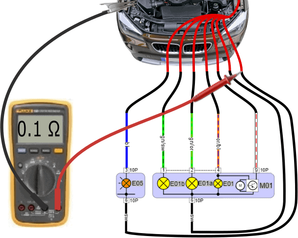
We always perform the resistance measurement last. The reason is that a switched-off lamp may be connected to ground on both terminals (positive and negative) via the switch. If you start with the resistance measurement, several positive wires will appear as ground. Only when the lamp is switched on does the ground change to a positive.
Ground-switched H4 lamp:
In this paragraph we have so far only discussed the positive-switched H7 lamp. We recognise this by the fact that the dipped-beam and main-beam lamps each receive a positive (12 volts) on their own wire to make the lamps light up.
We may also be dealing with a ground-switched H4 lamp. The three diagrams (to the right and below) relate to a switched-off H4 lamp containing:
- E01a: dipped beam;
- E01b: main beam;
- S21: light switch;
- S25: changeover switch between dipped and main beam;
- Ins: main-beam warning light in the instrument cluster.
With a properly functioning lighting system, we measure the system voltage (around 12 volts) on both the positive and negative terminals in the switched-off state. The voltage difference across the lamp is now 0 volts (on positive and negative). No current flows through the filament. The lamp is off.
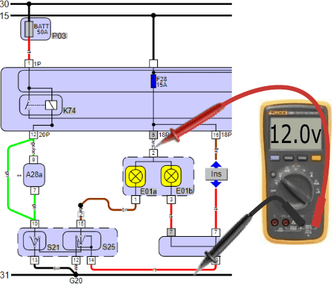
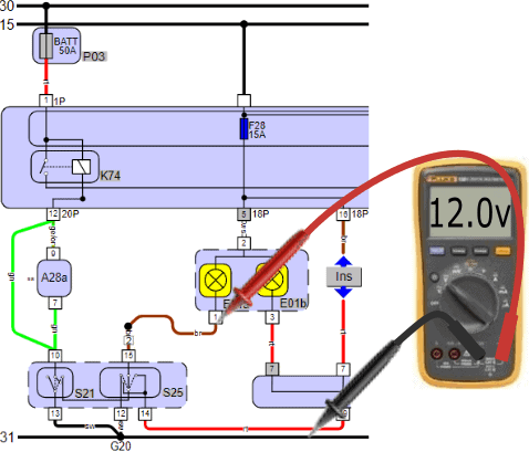

Switch S21 (lighting switch) supplies the switch next to it (S25) with a supply voltage when the lighting is switched off. When switching on, for example, the low beam, both S21 and S25 switch to ground. Using S25 (usually the indicator stalk on the steering column), the driver can switch either the low or high beam to ground. One of the two bulbs will illuminate.
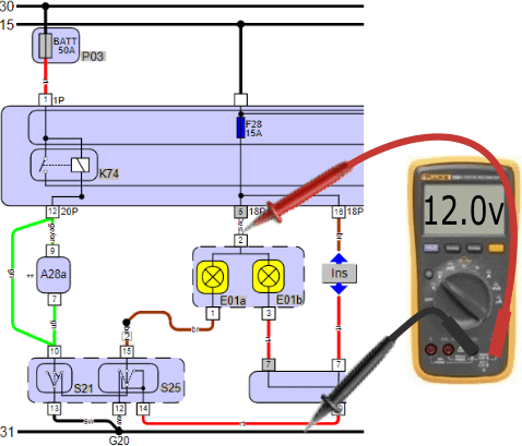
H4 bulb switched on:
The supply voltage of the bulbs is again 12 volts. The negative connections of the bulbs (low beam brown, high beam red) are switched to ground via switch 25.
- Low beam: with the low beam switched on, the voltage on pin 1 of the bulb relative to ground drops from 12.0 to 0.4 volts;
- High beam: when the high beam is switched on, the voltage on pin 3 drops to 0.4 volts.
Note: when the low beam is switched on, the high beam is off. At the moment that we measure 0.4 volts at the ground connection of the low beam, the voltage difference across the high beam is 0 volts (pin 3 then has 12 volts). This is also the case for the low beam: when the high beam is on, the voltage difference across the low beam is 0 volts. In short: when one is on, the other is off.
We are dealing with a ground-switched H4 bulb, but we measure 0.4 volts on the ground connection. This is because there is a small resistor in the switch which consumes the remaining 400 mV. When repairing and connecting the wire, this must be measured with the voltmeter, not with the ohmmeter!

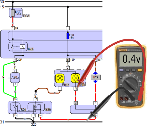
In the diagram we see a connection point under E01b where INS (instrument panel) is also connected. The instrument panel has a connection between the positive and negative of the high beam bulb. At the moment the high beam bulb is on (we measure 0.4 volts on pin 3), the high beam warning light in the instrument panel is also switched to ground. The warning light illuminates at the same time as the high beam. In the switched-off state, the voltage difference across the warning light is also 0 volts (12 volts on the positive and 12 volts on the negative), so no current flows through it.
Repairing headlamp wiring:
A repair can be carried out by connecting the wires, with the metal terminals (A) at the end, into the connector blocks (B and C) and finally pushing them together. The connector blocks shown are fine for use in the interior, but under the bonnet the uninsulated connectors are exposed to moisture, etc. Of course, insulated connector joints must be used here. The principle is the same, and the illustration serves as an example.
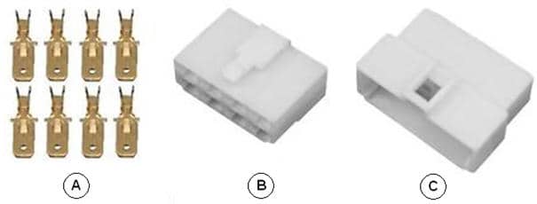
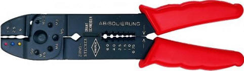
The metal terminals must be crimped onto the wire that has been stripped by approximately 1 mm; the copper wire must not be longer. We insert the end of the wire into the metal terminal and crimp the terminal onto the wire using a special AMP / cable-lug crimping tool (shown) or a ratchet crimping tool.
To make it easier for yourself when connecting, you can make a simple sketch showing connector positions 1 to 8 and the bulbs / adjustment motor in the headlamp.
In this example, the right indicator (R) is connected to pin 2, the side light / parking light (58R) to pin 5, the adjustment motor to pins 6 and 7, the high beam (56a) to pin 7, the low beam (56b) to pin 4 and the ground (31) to pin 3.