Introduction:
An LED is a widely used semiconductor component for emitting light. LED stands for Light Emitting Diode. After its invention in 1962, the LED was mainly used as an indicator light and for signal transmission. Technological developments have made it possible since the late 1990s to produce LEDs that serve as light sources for everyday use. In automotive engineering, LEDs are widely used as instrument lighting (dashboard), exterior lighting (taillights) or headlighting (in the headlamps) due to the following advantages compared to incandescent and halogen lamps:
- low energy consumption: at the same light intensity compared to other types of lamps, the LED consumes significantly less energy. The LED has a very high efficiency of up to 80%;
- safety: incandescent lamps need about 200 ms to bring the filament up to temperature and emit light. An LED does not need a warm-up phase, which means that an LED reaches its light intensity more quickly (in less than 1 millisecond). When an LED is used as a brake light, deceleration is noticed earlier and this has a positive effect on stopping distance;
- low heat generation: because LEDs hardly get warm, lamp housings can be made smaller and cheaper materials can be used that are less resistant to thermal loads;
- long service life: an LED lasts roughly the entire life of a car. If it appears that LEDs are defective, the cause is often found elsewhere, such as a break in the circuit board track or incorrect control. The brightness of an LED can decrease after a certain number of burning hours.
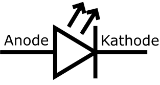
The image alongside shows the symbol of the diode, with additional text above the anode and cathode sides. The symbol of an LED is almost identical to that of a diode, but two upward-facing arrows are added, indicating the light emission. The current direction, just as with the diode, is in the direction of the arrow. The vertical bar is the blocking direction. If the current flows through the LED in the arrow direction (from left to right), it will light up. The other way around (from right to left) it will block and therefore not light up.
Operation of an LED:
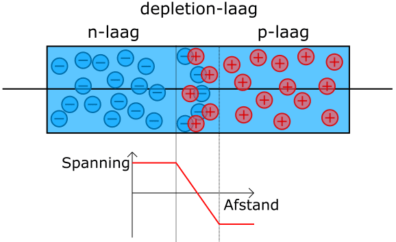
Just like a “normal” diode, the LED consists of two semiconductor layers:
- the negative layer (n-layer) contains an excess of electrons;
- the positive layer (p-layer) has a shortage of electrons.
The shortage of electrons in the p-layer can be seen as a surplus of positive holes. In the pn-junction (depletion layer) the excess electrons in the n-layer will fill the holes in the p-layer. No current flows yet, so the charge in the pn-junction is neutral.
To make current flow through the diode, the internal voltage of the depletion zone must first be overcome. This is the so-called diffusion voltage or threshold voltage of the diode. When the voltage is increased, the electron flow from the n-layer to the p-layer will be able to flow. In the depletion layer, however, part of these electrons is captured by the holes. These electrons then release part of their energy in the form of light flashes. The generated light can escape through the thin p-layer. The light intensity is determined by the current: the higher the current, the more intense the light.
The jumping of valence electrons from the negative to the positive layer produces the light emitted by the diode.
Forward voltage in relation to the color of the LED:
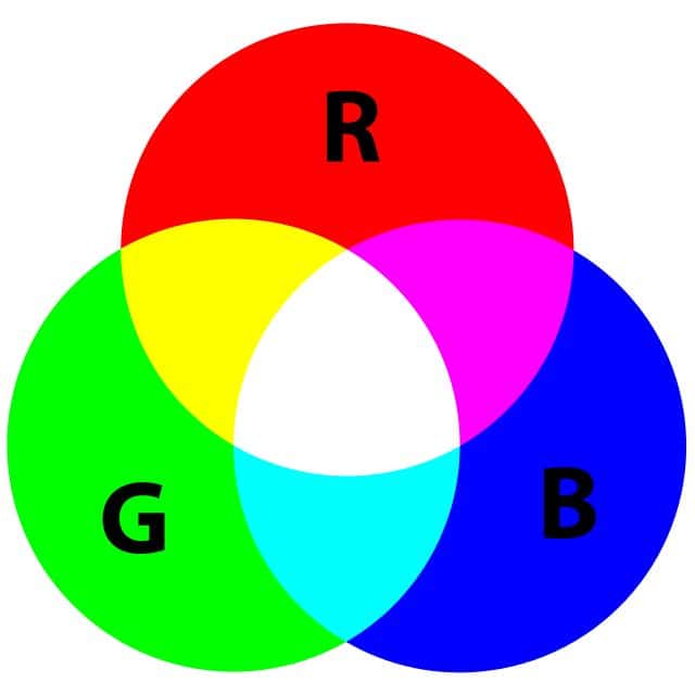
We find LEDs in three colors: red, green and blue. With these three primary colors, other colors can be obtained by mixing them. The composition of materials of the n- and p-layers determines the amount of energy in the electrons and holes.
- Low-energy electrons convert less energy into light radiation than a high-energy electron;
- Red light has less energy than blue light;
- Red is produced by low-energy and blue by high-energy electrons.
White LEDs cannot be produced directly. By adding an extra fluorescent layer to a blue LED, part of the blue light is converted into yellow light. The mixture of blue and yellow light is perceived by the human eye as white light. By adjusting the mixing ratio between this yellow and blue light, warm or cool white light can be emitted.
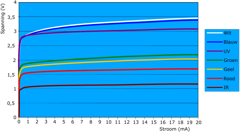
In the characteristic we see the voltage that is built up in the depletion zone and thus the forward voltage of the respective LED color. When current is driven through an LED, an almost constant voltage drop occurs.
Drive methods:
In automotive engineering we can drive LEDs with a series resistor or in series circuits, so that we achieve the desired drive voltage.
LED with series resistor:
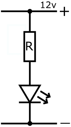
If we were to connect an LED directly to the positive and negative terminals of the battery, the LED would fail immediately. There must always be a series resistor placed in series with the LED.
The value of the series resistor is determined by two factors: the current and the supply voltage. A red LED emits light as soon as the operating voltage of 1.5 volts is reached and about 20 mA flows through it.
The applied supply voltage depends on the application. In automotive applications this may be 5, but also 12 or 24 volts. With Ohm’s Law the required resistance can be determined. Subtract the operating voltage from the supply voltage and divide this by the current.
- with a supply voltage of 5 volts, a series resistor for a red LED will be required of (5 – 1.5) / 0.02 = 175 ohms.
- with a supply voltage of 12 volts and a red LED: (12 – 1.5) / 0.02 = 525 ohms (a resistor of one step higher).
LEDs with a series resistor are mainly found in retrofitted LED lighting. The rapid switching times and brightness of an LED can be a reason to replace incandescent lamps with LEDs. You do not necessarily do it for energy savings, since the series resistor also causes a power loss that in some cases is just as large as the power dissipation of the original lamp.
LEDs connected in series:
By connecting the LEDs in series, no, or only a low-value, series resistor is needed. The internal resistance of the LEDs themselves ensures that the supply voltage is distributed across the LEDs in the series circuit. The more LEDs placed in series, the smaller the series resistor can be. In the image, six LEDs are connected in series and two rows are connected in parallel.
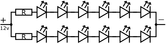
The LEDs connected in series are found in taillight units or third brake light units. This is a widely used drive method in automotive engineering.
Adjusting light intensity:
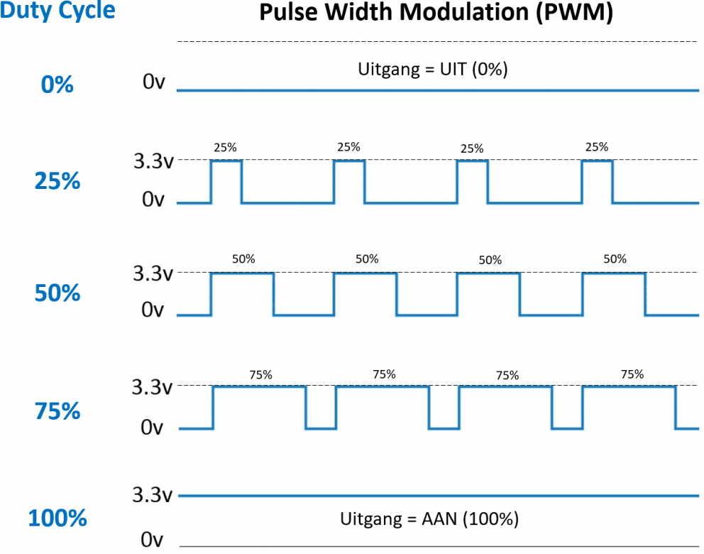
With a microcontroller we can control an LED with a pulse. This is called Pulse Width Modulation (PWM).
The duty cycle determines the time during which the LED is driven. By switching the on-off pulses between 3.3 and 0 volts at high speed, the LED will burn at a lower brightness.
This drive method is the same as for an incandescent lamp with multiple functions, for example:
- 50% brightness with the lights switched on;
- 100% brightness with the brake light switched on.
In a practical setup with an Arduino one can experiment with PWM control of the LEDs on the Arduino or externally connected LEDs (provided with series resistors).
Multi-color LEDs:
With the three primary colors red, green and blue, all colors can be created. This can be used effectively by combining two or three LEDs. Below, three principles are shown that are used to obtain multiple colors by means of an electrical circuit.
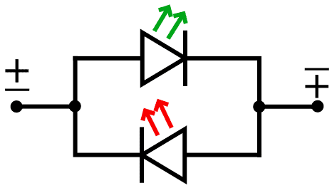
Two-color LED:
In the diagram there are two LEDs connected in parallel, with their blocking and forward directions reversed. The current direction determines which LED lights up: green (top) or red (bottom). The polarity is reversed by an external circuit or ECU.
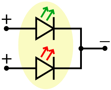
Three-color LED:
In this diagram, too, there are two LEDs connected in parallel. In the circuit, a supply voltage can be applied to one of the two LEDs (green or red), or both at the same time. In that case, color mixing occurs and the red and green LEDs appear yellow.
RGB LED:
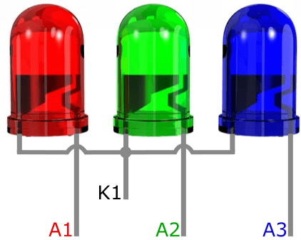
With RGB LEDs, three LEDs, each with its own color, are housed in one package. The colors can be controlled individually. To drive the RGB LED, three PWM controls are needed, each generating an adjustable on/off ratio on its respective supply pin. In addition to the different colors, the light intensity can also be adjusted.
In the following image we see three LEDs, each with its own anode connection (A1 to A3) and a common cathode.