Introduction:
Information processing in modern motor vehicles takes place for the most part, if not entirely, digitally. The digital information consists of electrical voltages, where a yes/no or on/off is formed on the basis of the voltage level. In the interface electronics there is an A/D converter (Analog / Digital) where a sensor voltage is converted into a digital message, which consists of ones and zeros.
In digital electronics we speak of a logic 1 or a logic 0. The voltages are at TTL level (Transistor Transistor Logic).
- Yes or on: logic 1: 5 volts
- No or off: logic 0: 0 volts
Basic electronic circuits on ECUs contain many ICs with which logical circuits are made. These logical circuits contain logic gates, which can be controlled in hardware or software by the CPU.
Logic gates:
The ALU (Arithmetic Logic Unit, Dutch: rekenkundig-logische eenheid) is the central part of the microprocessor in an ECU. The ALU performs arithmetic and logic operations. The ALU also determines where in memory the next instruction of the program to be executed is located.
The ALU contains logic gates that are mostly made of silicon semiconductors. The logic gates can perform operations within a few nanoseconds by means of a binary code; a combination of ones and zeros. This gives an instruction with two possibilities: on or off, conducting or non-conducting. Multiple instructions are processed simultaneously in the ALU and work together using 8, 16 or 32 bits to form what is called, according to computer architecture, a “word”. A word is the largest amount of data stored in a single data register. This is the amount of data that can be processed by the processor in one go.
The following basic operations take place in an ALU:
- shifting one or more bit positions to the left or right (shift)
- performing arithmetic operations on two words, such as adding or completing (add);
- performing logical operations on the data (AND, OR, NOT, NAND, NOR, XOR, XNOR).
In the images below, the ALU is shown as a symbol (left) and with the IEC symbols that translate the operation of A and B (incoming) to R (outgoing).
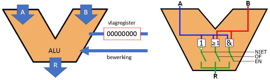
The NOT, OR and AND gates that we see in the ALU on the right are the most common gates with which logical operations are performed. There are gates that are an addition to these three basic gates. We will come back to this later on this page. With the NOT, OR and AND gates, outcomes of inputs can be pre-programmed. By means of a circuit that sets an answer such as yes/no or true/false for, for example, the handbrake warning lamp, the lamp can be activated on the basis of two inputs.
- is the handbrake applied?
- is the brake fluid reservoir level sufficient?
If one or both answers can be answered with “yes”, the warning lamp is activated. More examples follow later on this page.
The table below shows these three basic gates. On this page we will mainly use the English names (AND instead of EN) to avoid creating confusion for you as the reader, but both are of course correct. The same applies to the symbols (IEC and ANSI). We use the IEC symbols, but mainly see ANSI symbols in American literature. Again, do not mix them up and use only one type of symbol.
Below the table an explanation is given of the characteristics of each gate and the truth table shows with which inputs you get an output of 0 or 1.
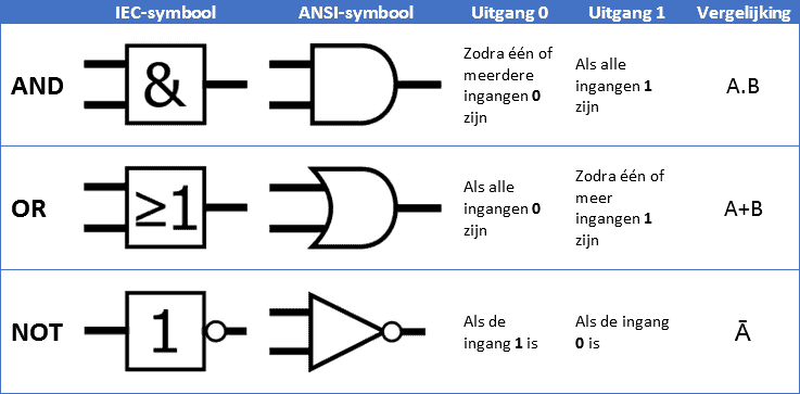
Below is the explanation of the three gates with the symbol and the truth table, in which the outputs are shown for different input combinations.
AND gate:
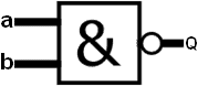
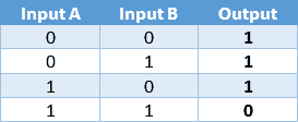
The AND gate (Dutch: EN-poort) can have multiple inputs, but always has only one output. In the image we see inputs a and b. On both inputs it is possible, independently of each other, to set a 1 or a 0. The output (Q) becomes 1 when both inputs (a and b) are 1. In all other cases the output Q is 0.
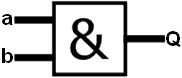
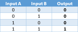
- With two inputs of the AND gate (in this case input A and B) there are four possible configurations to generate an output. These are shown in the truth table to the right of the image of the AND gate.
- With four inputs there are 16 possibilities;
- With eight inputs there are even 256 possibilities.
OR gate:
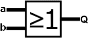
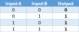
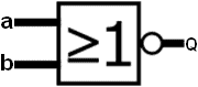
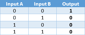
The OR gate (Dutch: OF-poor) can also have multiple inputs, with one output. With an OR gate the output is 1 if one of the two inputs is a 1, or if both inputs are a 1.
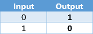
NOT gate:
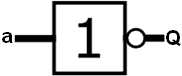
The NOT gate (Dutch: NIET-poort) functions as an inverter and has only one input and output. The input signal is inverted: when the input signal is 1, the output signal becomes 0 and vice versa.
In addition to the mentioned circuits (AND, OR and NOT) we also know a number of derived logical circuits. With these circuits we can combine two of the circuits discussed earlier into one circuit.
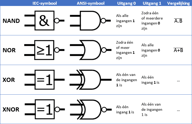
NAND gate:
The Not-AND gate (Niet-EN-poort) is an AND gate followed by a NOT gate. The output is 1 if there is a 1 on multiple inputs. Only when there is a 1 on all inputs is the output 0. This is exactly the opposite of the AND gate discussed earlier.
NOR gate:
The Not-OR gate (Niet-OF-poort) is an OR gate followed by a NOT gate. It can have multiple inputs and has only one output. In this circuit the output will only be 1 when both inputs are 0.
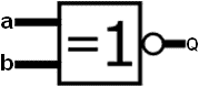
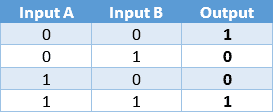
XOR gate:
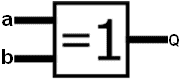
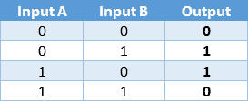
The eXclusive-OR gate is a gate whose output is 1 if only one input is 1. When both inputs have the same logical state, the output becomes 0. The XOR gate never has more than two inputs.
XNOR gate:
The eXclusive-OR gate is here provided with a NOT gate, which makes it an eXclusive-NOT-OR gate. The output is inverted compared to the XOR gate.
For each IC it is important that both a power supply and ground are connected to create a closed circuit. Both gates must also receive a voltage to prevent a floating measurement. To ensure that the inputs and outputs switch properly, pull-up and pull-down resistors are needed. Without these resistors the gates may remain “active” while they are not being controlled. The gates are then not reliable.
Combinational circuits and automotive applications:
The digital ICs can be connected together by connecting the output of one IC to the input of the other IC. With these combinations, circuits can be made with which, for every desired input combination, a desired output combination is obtained. When several ICs are connected together, we speak of a combinational circuit. To get a bit of a feel for the combinational circuits, automotive examples follow below.
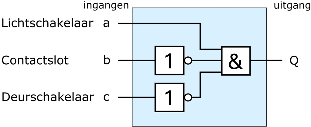
Light warning circuit:
A practical example of a combinational circuit is that of the light warning system. At the moment when the ignition is switched off and the door is opened while the exterior lighting is on, the driver must be warned of this by means of a buzzer. For the three input signals the AND gate is used. As described in the previous paragraph, all inputs of the AND gate must be 1 in order to get a 1 at the output and activate the buzzer. If one of the three inputs of the AND gate is a 0, the output remains 0 and the buzzer remains off.
- Light switch: with the switch off, a 0 appears at input a. When the parking or dipped beam is switched on, this becomes a 1;
- Ignition switch: with the ignition switch on, a 1 appears at input b. With the ignition switch off, a 0 appears. The NOT gate in this case inverts the 0 into a 1 to obtain the correct signal for the AND gate.
- Door switch: when a door is open, the signal is switched to ground. As with the ignition switch, the 0 must be inverted to a 1 in order for the AND gate to function properly.