Introduction:
In automotive engineering, Hall or magneto-resistive sensors are often used. These sensors have the task of measuring the speed and transmitting it to the relevant control unit. On this page, the operation and applications of the Hall sensor are described.
Operation of the Hall sensor:
A Hall sensor works by means of magnetism. There are 2 types of Hall sensors, each with its own operation:
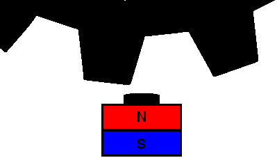
Hall sensor with permanent magnet:
Due to changes in the air gap, a varying magnetic field is created in the Hall sensor, which then generates the varying Hall voltage. This type of Hall sensor is often used as a speed sensor, for example at the crankshaft gear. The engine speed of the crankshaft is transmitted to the ECU, which uses it to control the ignition, and to the instrument cluster to drive the tachometer.
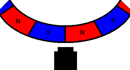
Hall unit with magnetic disk:
With this type of Hall sensor, a disk with magnets rotates past the mounted Hall unit. The rotation of the magnetic disk creates a varying Hall voltage. This type of Hall sensor is often used as an ABS wheel speed sensor. Compared to the system with a toothed ring, this system has the great advantage that it works at a lower speed. Because of the rotating magnetic disk, a correct speed can already be registered at a slowly rotating wheel (below 5 km/h), which was not possible with the toothed ring system.
The magnetic disk is integrated into the wheel bearing. These cannot be replaced separately.
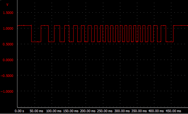
An oscilloscope can be used to display the voltage pattern of the Hall sensor. Below is a scope image of an ABS sensor, which is designed as a Hall sensor. The frequency changes as the wheel speed changes (the square wave becomes wider or narrower). The amplitude (the height of the signal) remains the same.