Introduction to planetary gear set:
A planetary gear set is a type of transmission that consists of three main components:
- Sun gear: This is the gear in the center of the system.
- Planet gears (smaller gears): These are connected to each other on a carrier and rotate around the sun gear. Usually there are three or four planet gears.
- Ring gear: This is a gear with internal teeth that surrounds the planet gears.
In a planetary gear set, the planet gears move around the sun gear while also rotating about their own axis. This motion is guided by a planet carrier, also called the carrier, which holds the planet gears in position. Depending on which component is fixed and which component provides the drive, the planetary gear set changes the output speed and thus also the torque via different gear ratios and directions of rotation.
A planetary gear set is used to improve power transmission: the system can handle large forces despite its relatively small size.
Planetary gear sets are often used in cars where the speed is reduced and the torque increased, such as in the automatic transmission, hub reduction and the mechanism in the starter motor for the combustion engine.
In a car with an automatic transmission, the planetary gear set provides the different gears.
Calculating gear ratios of a single planetary gear set:
A planetary gear set consists of at least one set of gears, each with a sun gear (Z), a carrier (D) with three planet gears and a ring gear (R). Next to this, an image of a gear set is shown.
With a planetary gear set, one or more gear ratios can be achieved:
- one part is driving
- one part is driven
- one part is fixed (stationary)
- or 2 parts are coupled together: i = 1 : 1
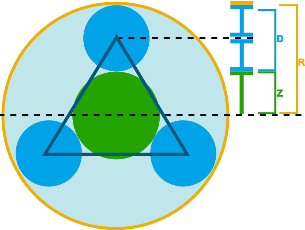
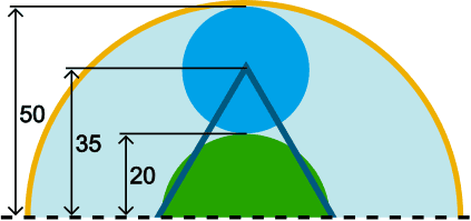
On this page we look at the ratios that arise from the different number of teeth on the carrier, planet gears and the ring gear. To get started with this, we focus on the upper part of the planetary gear set (above the dashed line), and the numbers of teeth are known:
- ring gear: 100 teeth (above the line 50)
- sun gear: 40 teeth (above the line 20)
- planet gears: each (100+40)/2 = 70 teeth (from the line to the center 35)
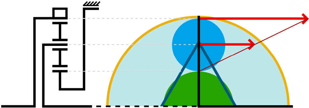
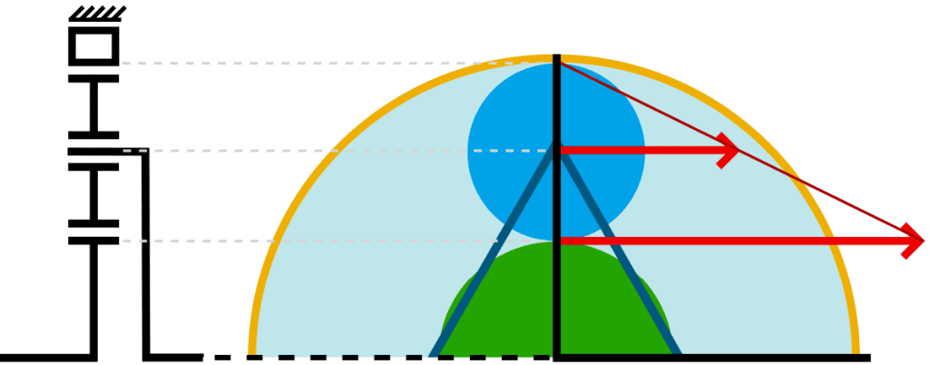
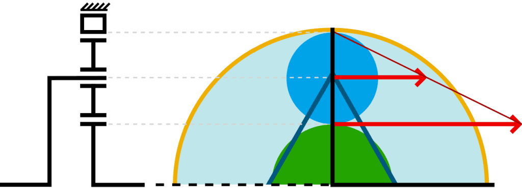
Below, the six transmission possibilities of a single planetary gear set are shown. On the left side of the figures there is a diagram in which the input energy (e.g. from the engine) enters the set, and leaves it via the right side of the set. Next to the diagrams, the upper sides of the set are shown, with the forces indicated by red vectors with a connecting line. Where the connecting line touches the Y-axis (at half the sun gear), the set is fixed to the housing.
Possibility 1:
- Sun gear fixed
- Ring gear is driving
- Carrier is driven
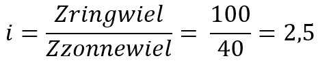
Calculating the gear ratio:
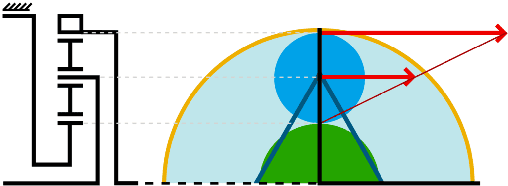
Possibility 2:
- Sun gear fixed
- Carrier is driving
- Ring gear is driven
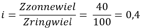
Calculating the gear ratio:
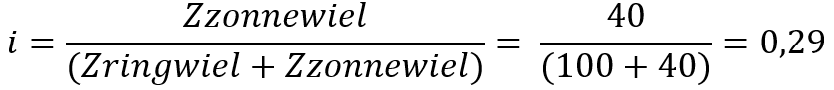
Possibility 3:
- Ring gear fixed
- Carrier is driving
- Sun gear is driven
Calculating the gear ratio:
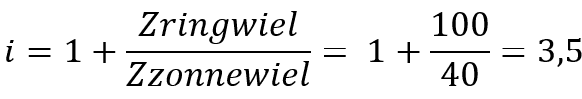
Possibility 4:
- Ring gear fixed
- Sun gear is driving
- Carrier is driven
Calculating the gear ratio:
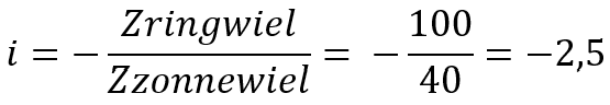
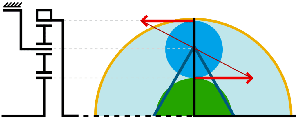
Possibility 5:
- Carrier fixed
- Sun gear is driving
- Ring gear is driven
Calculating the gear ratio:
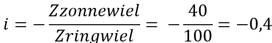
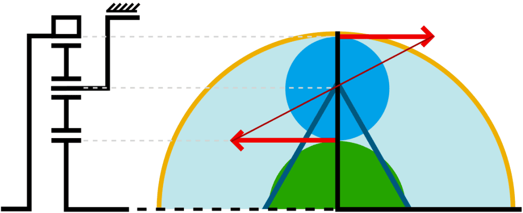
Possibility 6:
- Carrier fixed
- Ring gear is driving
- Sun gear is driven
Calculating the gear ratio:
Calculating gear ratios of multiple planetary gear sets:
A conventional automatic transmission works by shifting between the different planetary gear sets; see the chapter automatic transmission.
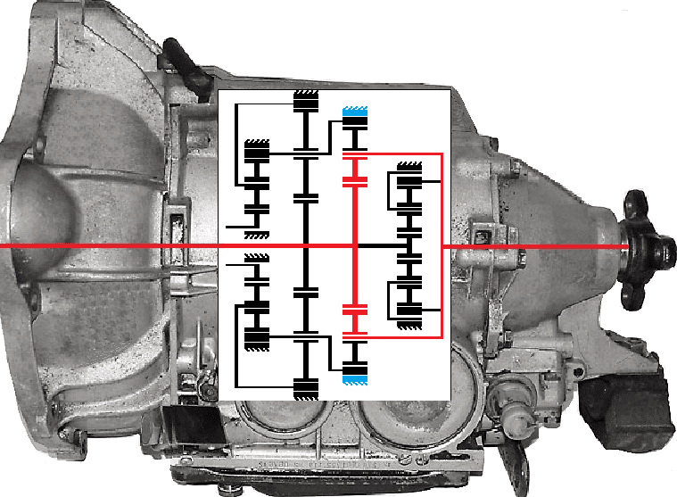
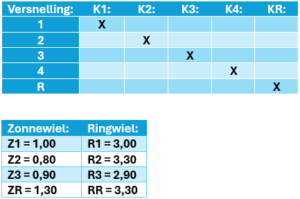
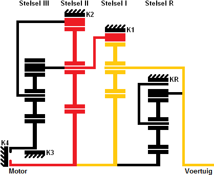
Below is a schematic representation of four sets of planetary gear sets in an automatic gearbox. There are three sets for the forward gears and one for reverse. The red line indicates the direction of the forces through the automatic gearbox; from the left (engine side with torque converter), through the complete section with planetary sets (black lines) to the coupling of the propeller shaft. If you look closely at the sets in the gearbox, you will see that the image above is derived from this. Four sets are used in the gearbox, each with a Z, D and R (sun gear, carrier and ring gear).
The planetary gear sets are symmetrical above and below the centerline. To gain insight into what happens when a gear is engaged, the driven parts in the planetary set in the figure below have also been made red:
In the figure above, first gear is engaged. To engage first gear, a clutch must be engaged. This clutch is shown in blue and locks the ring gear to the housing. With the clutch closed and one side of the planetary set driven, one part must also start to rotate. The dimensions of the components then determine the gear ratio (think of a small input gear and a large output gear; the large gear will then rotate more slowly. If the large gear had twice as many teeth as the small gear, the ratio would be 1:2). The dimensions of the ring gear, the sun gears and the planet gears are different for all four sets, so that multiple gear ratios can be achieved.
Later on this page, images, explanations and calculations will clarify how the planetary gear sets in the automatic gearbox are shifted while driving and shifting.
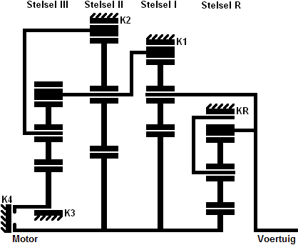
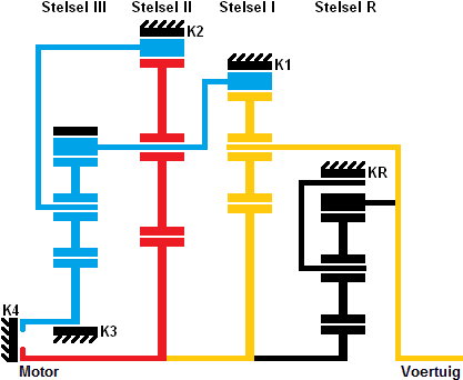
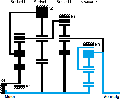
We will now look at the upper half of the gearbox, since the gearbox is symmetrical when viewed from the center. From this figure we will later determine the gear ratios on the page. Above the four sets is shown which number the set has; I, II, III and R (reverse).
Each set has its own Z, D and R. That is not indicated in the figure, but if you look again at the image at the top of this page you will recognize it. Later on this page this will be taken as known.
At the bottom left of the figure you can see clutch “K4” shown. This clutch ensures that two sides of the set are connected to each other at the same time; set 3 is connected to sets 1 and 2. No other clutches are closed, so the entire set is “locked”. The engine speed is transmitted 1 to 1 to the wheels of the vehicle, without there being a gear ratio; we call this direct drive. This is in fourth gear.
In cars with a manual gearbox, fourth gear is often also direct drive. There too, the engine speed is passed on 1 to 1 to the wheels.
The difference in speed between the input shaft (engine or torque converter) and the output shaft (vehicle) is called the gear ratio.
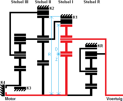
First gear is engaged.
By fixing the carrier of set I (using clutch K1), a force can be transmitted from the sun gear to the carrier. The carrier is connected to the driveline, so there is now a direct connection between the engine – via the planetary gear set – to the gearbox. The dimensions of the components in the planetary gear set provide a gear ratio.
The red lines indicate the force path. The blue lines indicate everything that is fixed when clutch K1 is energized. Not only is the carrier of set 1 fixed, but also the carrier of set 3 and the sun gear of set R are blocked.
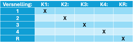
As explained, clutch K1 is energized when shifting into first gear. When shifting to second gear, clutch K1 will be disengaged and another clutch will be energized. This can be seen in the table.
When shifting to second gear, clutch K2 will be energized. The ring gear of set 2 is then fixed. Because the sun gear of set 2 is fixed and the sun gear is driven, the carrier will start to rotate. This carrier will in turn drive set 1. In set 1, this time the ring gear is not blocked, but driven by another set. The output speed (vehicle line) will therefore be lower than when first gear was engaged.
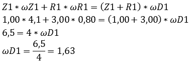
Calculating the gear ratio of first gear:
According to the table below, clutch K1 is closed. So the ring gear is locked. The driving force from the engine goes through the sun gear and via the carrier to the vehicle. The ratios are also given, namely 1.00 for the sun gear and 3.00 for the ring gear of set 1. We will use these values.
The basic formula for calculating the gear ratios of planetary gear sets is as follows:
ω stands for omega and is the angular velocity during rotation.
Because we are calculating with set 1, we put a 1 behind everything. For the next sets we change this number. Especially with multiple sets (where one set drives the other) it must be written this way, because otherwise it becomes very unclear.
Below is the diagram of first gear. For clarity, the Z (sun gear), D (carrier) and R (ring gear) are drawn in blue.
We now fill in the basic formula for the first set. The omegas are unknown and the carrier is stationary. So we cannot fill in anything for that. The Z1 and D1 are known, so we do fill those in. R1 is stationary, so we cross it out. We also do not fill in anything for it in the formula.
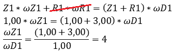
You can now see that the gear ratio of first gear is 4.
In automotive engineering that never happens; it would always be slightly above or below 4, because otherwise the gears would always mesh on the same faces (extra wear). But here it is easier to use as an example for calculations. You can also now see that the omegas are known!
ωZ1 = 4
ωD1 = 1
These omegas are the angular velocities of the shafts in the set. For first gear the omegas are not yet very important, but when calculating double-driven sets (as will soon become clear with second gear), they are important.
Calculating the gear ratio of second gear:
When calculating the gear ratio of second gear, you must take into account that the first gear set is double-driven; the sun gear of gear set 1 is driven by the engine and the carrier is driven by gear set 2. This now results in a different vehicle speed than in the situation where the ring gear was stationary (as with first gear).
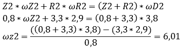
We always start the calculation with the gear set that is driven only in a single way. In this case that is gear set 2, because it is driven solely by the engine via the sun gear.
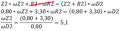
The ratio produced by the second gear set is 5.1. This is not the ratio between the engine and the wheels, but between the engine and gear set 1. Now we are going to calculate the gear ratio of gear set 1 using the data from gear set 2, because the omegas are now known:
ωZ2 = 4.1
ωD2 = 0.8
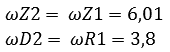
If you look at the diagram now, you will see that the sun gears of gear sets 1 and 2 are rigidly connected. The carrier of gear set 2 and the ring gear of gear set 1 are also connected. The omegas of the connected parts are the same, so we can say:
ωZ2 = ωZ1 = 4.1
ωD2 = ωR1 = 0.8
It is very important to look at this carefully! Always follow the lines in the diagram.
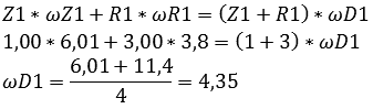
We now insert these omegas into the calculation for gear set 1.
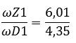
We can now determine the final overall ratio by dividing the input omega by the output omega. If we look at the diagram, we can see that the omega of the sun gear of gear set 2 is the input, and the omega of the carrier of gear set 1 is the output.
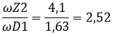
The total gear ratio of second gear is therefore 2.52.
Calculating the gear ratio of third gear:
When calculating third gear you must take into account that all three gear sets work together. Always start with the gear set that is driven only in a single way. In this case that is the third:
The sun gear of gear set 3 is fixed, so it does not participate. Then fill in the remaining values:
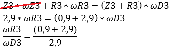
With that we obtain:

Then we move on to gear set 2. The omegas that are known for gear set 3 are entered into the calculation for gear set 2:
Now we move on to gear set 1. Here too, the known omegas are filled in:
Ultimately we obtain:
That means that the total gear ratio of third gear is 1.38.
Calculating the gear ratio of fourth gear:
In fourth gear clutch K4 is engaged. This means that the sun gears of gear sets 1, 2 and 3 are simultaneously connected to the engine. The complete system is now locked. All omegas are equal to each other.
If all omegas are equal, no gear ratio is possible. The engine speed is transmitted directly to the wheels. This is called prise-direct.
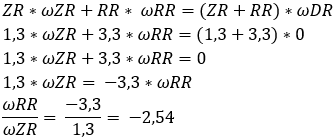
Calculating the gear ratios of reverse gear:
Reverse gear is usually obtained by locking the carrier. That is also the case in this gear set. By locking the carrier, the input motion is reversed and the output shaft rotates in the opposite direction. In this gear set the sun gear is driven and the carrier is the driven member.
When calculating the ratios, just as with first gear, we do not need to take any other gear sets into account: reverse gear is a single gear set. Below are the formulas in which the omegas of the ring gear and the sun gear are ultimately divided by each other. The negative number (-2.54) indicates that reverse gear is engaged.