Introduction:
The advantages of the automatic transmission are increased ease of use, comfort and safety. Changing the gear ratio takes place as smoothly as possible, without jolts. The automatic transmission shifts up to a higher gear sooner under light throttle than when the accelerator pedal is fully depressed. In the latter case, it will only shift up shortly before the rev limiter. When the vehicle comes to a standstill, it automatically shifts back to first gear.
Between the engine and the automatic transmission there is a fluid coupling or a torque converter. See the separate chapter koppelomvormer (torque converter).
Selector lever / mountain gears:
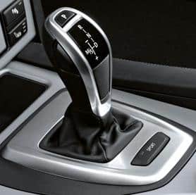
A car with an automatic transmission has a selector lever. By first pressing the brake pedal, the selector lever can be operated. Here is an overview of its functions:
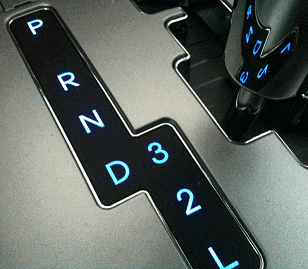
- P: Park (The output shaft is locked, the car can no longer roll away and the engine can rev)
- R: Reverse
- N: Neutral (The car is in neutral, the output shaft is not locked, so with the brake pedal released it can roll away)
- D: Drive (The forward gear; when accelerating, the car will automatically shift up and down)
- *S: Sport (The car will shift up later, so there is more acceleration when suddenly pressing the accelerator)
- *M: Manual (This allows the driver to indicate when it should shift up or down by moving the selector lever forwards or backwards to the + or -).
* is often an option and is not present on every automatic.
Other car brands use the positions L, 2 and 3 to allow the driver to choose which gear the car should stay in. These positions are also called the “mountain gears”.
If one of these positions is selected, the automatic transmission is put and held in a certain gear. This can be very useful when driving in the mountains. If you descend in the normal “D” position, the transmission will shift up to a higher gear. As a result, the gear ratio in the transmission becomes smaller and the car will descend increasingly faster. By selecting gears 3, 2 (1 or L), the transmission will run in a lower gear (e.g. from 5th to 4th). The engine then runs at a higher speed, causing the car to decelerate. The brakes no longer have to be applied constantly because more engine braking is used. When driving with a trailer, this is essential on steep descents, otherwise the brakes will overheat due to continuous braking.
Single planetary gear set:
Planetary gear sets are used in several systems, namely in automatic transmissions, starter motors, overdrives and hub reductions. A planetary gear set consists of the following components:
- Ring gear
- 3 Planet gears
- Carrier
- Sun gear
To be able to transmit torque with a single planetary gear set, the ring gear, the carrier or the sun gear must be locked. This component then acts as the reaction element. The planet gears only serve to bridge the distance between the sun gear and the ring gear.
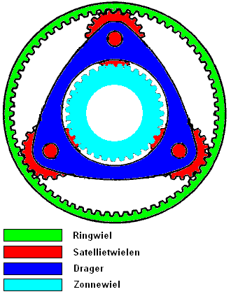
Example: The sun gear is connected to the engine and rotates at the same speed. The carrier is connected to the output shaft. The ring gear is fixed to the transmission housing. This creates a strong reduction. That means: the sun gear is the driving element, the ring gear is the reaction element and the carrier is the driven element.
The sun gear (light blue, in the middle) rotates counterclockwise. It drives the (red) planet gears which rotate clockwise. These rotate inside the ring gear and carry the (blue) carrier along.
As a result, the carrier will rotate more slowly than the sun gear. That means that the motion is reduced.
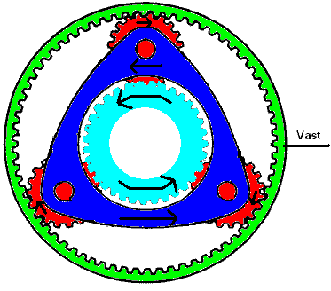
The table shows 6 different transmission possibilities. Not all of these are usable in automotive engineering. Usually only 3 possibilities remain.
For coupling and locking the different elements, brake bands or multi-plate clutches are used. In this way we can connect different elements and create reductions, overdrives and changes in direction of rotation.
In the latest systems, the computer ensures that oil pressure is supplied to the multi-plate clutches, allowing the components to be locked. The theory behind brake bands and multi-plate clutches is discussed further down on this page.
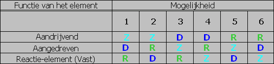
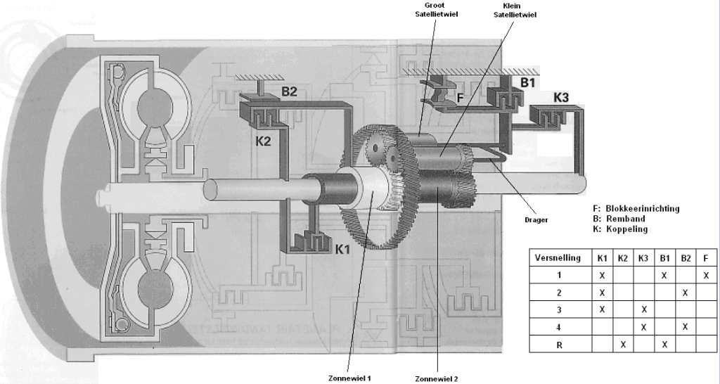
The image shows a schematic representation of four sets of planetary gear trains in an automatic transmission. There are three sets for the forward gears and one for reverse. The red line indicates the direction of the forces through the automatic transmission; from the left (engine side with torque converter) through the complete part with planetary sets (black lines) to the prop shaft coupling. Four sets are used in the transmission, each with a Z, D and R (sun gear, carrier and ring gear).
On the page reducties van planetaire tandwielstelsels berekenen (calculating reductions of planetary gear sets) you can find more information about engaging and disengaging planetary sets and linking various sets together.
The planetary gear sets are symmetrical above and below the center line. This cannot be otherwise, because during driving the internal parts are rotating.
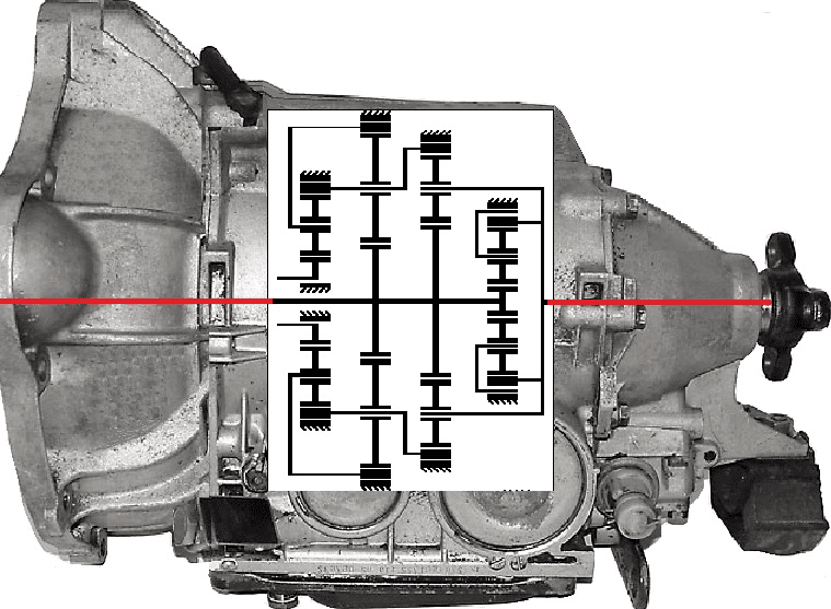
To provide insight into what happens when a gear is engaged, the driven parts in the planetary system in the image are also shown in red.
In the image, first gear is engaged. To engage first gear, a clutch must be engaged. This clutch is shown in blue. With the clutch closed and one side of the planetary system driven, another part must also start to rotate. The sizes of the components then determine the gear ratio (think of a small input gear and a large output gear; the large gear will then rotate more slowly. If the large gear had twice as many teeth as the small gear, the ratio would be 1:2).
In principle, this also applies to the automatic transmission; the sizes of the ring gear, the sun gears and the planet gears are different for each of the four sets. You can probably imagine that when a different clutch is actuated (e.g. of the set on the left) the speed of the output shaft will change. Click here for more information about calculating reductions of the planetary gear set.
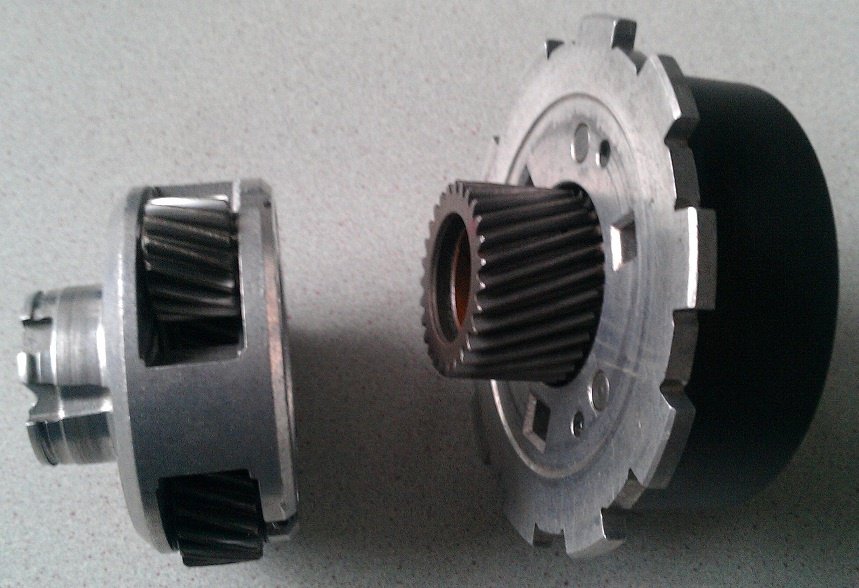
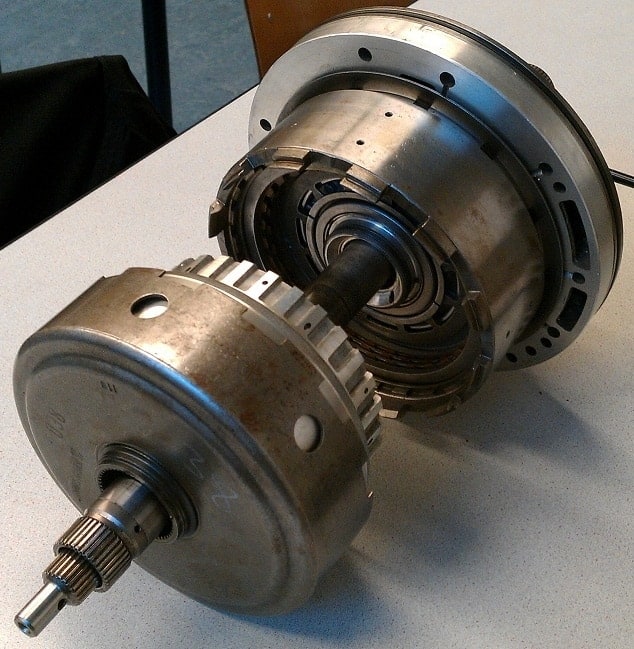
Combined planetary gear set (Simpson set)
In automatic transmissions, combined planetary gear sets are often used in which multiple planet gears or carriers are mounted on one sun gear. This is the case, among others, with the so‑called Simpson sets.
The Simpson set has a wide sun gear and 2 ring gears. These ring gears are usually the driven components, which results in much lower tooth loading than with a driven sun gear. Because of this, the set can often be made smaller. Nowadays, Simpson sets are not used very often. The Ravigneaux set is more popular among developers because it saves more space.
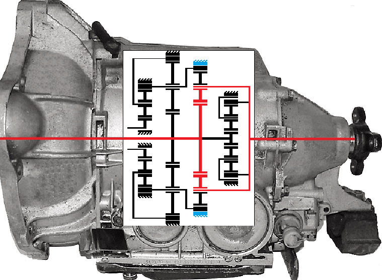
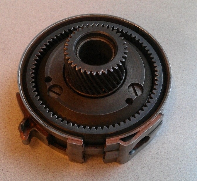
The image shows the planetary gear set as one closed unit. Visible are the ring gear (the wide ring with teeth on the left) and the carrier (the silver part).

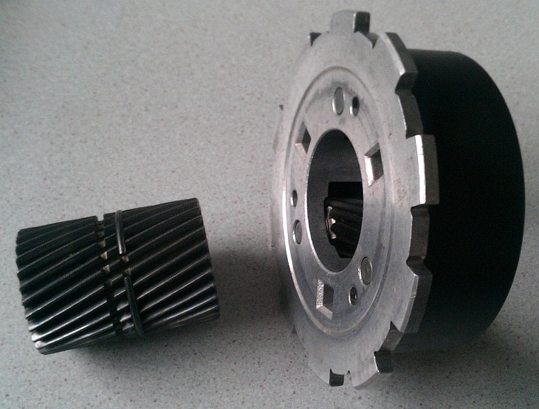
The ring gear has been slid off. Now the planet gears and the carrier are visible. The 3 planet gears engage on the inside with the sun gear and on the outside with the ring gear (which has now been removed). These gears are always in mesh with each other.
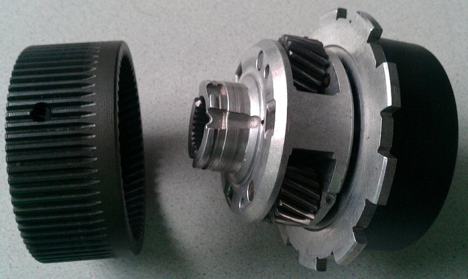
Here the carrier (with the planet gears) has been slid off the sun gear. The sun gear is the gear in the right-hand section.
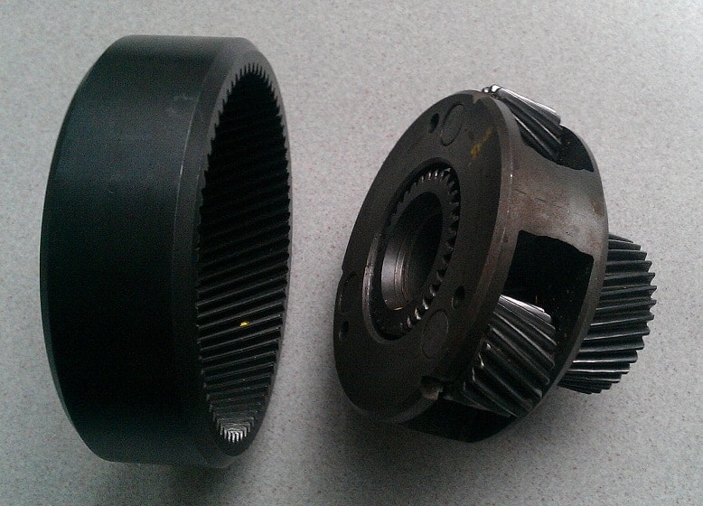
Here the double sun gear can be seen. The left part drove the planetary gear set that is shown in the images above. The right gear drove the set next to it. This is what gives it the name “combined” gear set, in other words, the Simpson set. If the sun gear is single (only the left part) and there is only one planetary gear set present, this is called a single or Ravigneaux set. The Ravigneaux set has 6 planet gears instead of 3 in this set, but that will be explained later.
This is the other part of the combined set. The black ring gear on the left, the carrier with the planet gears in the middle, with the sun gear on the right (inside it).
Combined planetary gear set (Ravigneaux):
The French engineer Paul Ravigneaux developed a compact planetary gear set in the late 1920s to create multiple practical gear ratios in a simple way. This is called the Ravigneaux set. This set is now used in many automatic transmissions.
This system is very compact, because 2 planetary gear sets are combined into just 1 set. It consists of 2 sun gears, 3 large and 3 small planet gears and 1 ring gear. A side view is shown alongside.
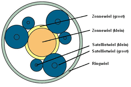
In the image below you can see that the planet gears mesh with each other. The large planet gear is connected to sun gear 1. The small planet gear is connected to sun gear 2.
In the table we see that when first gear is engaged, clutch 1 (K1) and brake band 1 (B1) engage. That means that sun gear 2 and the carrier with the planet gears are locked (these are driven). The ring gear is then the driving component.
This provides the greatest reduction. A large reduction also means a torque increase and at the same time a low speed at the wheels. First gear is the best gear for pulling away from standstill.
When the transmission shifts to second gear, brake band B1 is released and clutch B2 engages. Now sun gear 2 and the ring gear are locked and thus driven. In that case the carrier is the driven component. This combination of connected components provides a smaller reduction than in first gear and gives exactly the right gear ratio for second gear.
Multi-plate clutches and brake bands:
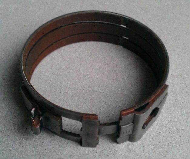
To lock the various components (such as the sun gear, the carrier and the ring gear), brake bands were used in older transmissions. Brake bands are made of iron and are lubricated to prevent metal-to-metal contact as much as possible and to provide cooling. In the images below you can see a brake band (left) and a brake band around the ring gear (right).
By using a hydraulic plunger (which extends) to clamp the brake band, the ring gear is locked. When it is locked, a certain part in the planetary gear set becomes the driving and driven part, which engages a gear.
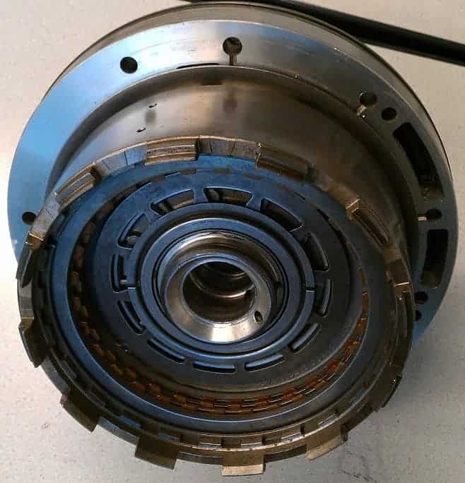
In newer gearboxes, brake bands are often no longer used, but multi-plate clutches. A multi-plate clutch consists of a number of separate clutch plates placed one behind another, which are pressed together by means of oil pressure. This “engages” the clutch and locks the ring gear. The images below show the multi-plate clutches in disassembled condition. The sections are slid into each other. The teeth of the steel housings mesh with each other.
Transmission oil:
Automatic transmission oil is usually of the ATF (Automatic Transmission Fluid) type, but sometimes manufacturers use a different type of oil with different specifications. This must therefore always be checked carefully, because using the wrong oil in the transmission can cause extra wear and premature failures. The oil level of the automatic transmission must also be checked periodically. If it is too low, the oil can overheat, causing it to age much faster, resulting in increased gearbox wear. Checking the oil level can sometimes be very simple by means of a dipstick, just like when checking the engine oil, but often the gearboxes do not have a dipstick. In that case, the oil level must be checked by, with the engine running, unscrewing the filler plug and topping up until the oil just runs out. Depending on the manufacturer, the temperature must first be checked. Sometimes it must be done with the oil as cold as possible, sometimes with oil between 30 and 50 degrees Celsius.
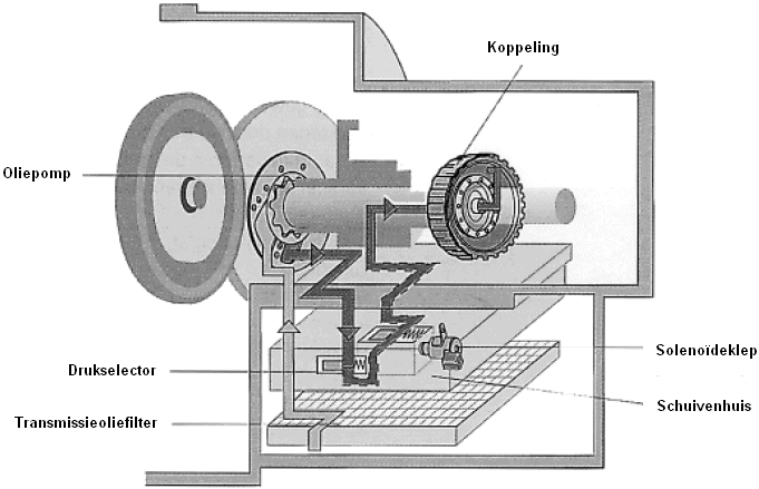
Oil pump:
A gear pump or crescent pump is often used in the transmission. The pump in the image is a crescent pump. This pump is driven directly by the engine. The oil therefore always circulates when the engine is running, in all positions in which the selector lever is located.

Control unit:
The control unit ensures that the pump pressure is constantly regulated to a base pressure. Furthermore, the control unit ensures that the control valves switch on and off at the right moment.
Control valves:
The control valves are operated by the position of the selector lever. In positions P and N the passages are closed and the oil drains from all lines. All clutches and brake bands thereby lose their oil pressure and are pushed back by spring force. When the control unit sends a signal (e.g. to lock the ring gear for first gear), a signal is sent to the solenoid valves (also called solenoid valves). When a valve, and with it a spool in the valve body, opens, oil under high pressure flows to a plunger that supplies the multi-plate clutch or brake band with oil. The pressure selector is a modulating valve that regulates the fluid pressure based on the accelerator pedal position. Due to this oil pressure, a component in the automatic transmission is locked, enabling a gear change.
Related pages: