Topics:
- Injection system
- Ignition system
- Idle control
Injection system:
The BMW engine was already equipped with a multipoint injection system. In this case, we do not need to look for suitable injectors and modify the intake manifold, as we did with the Land Rover project.
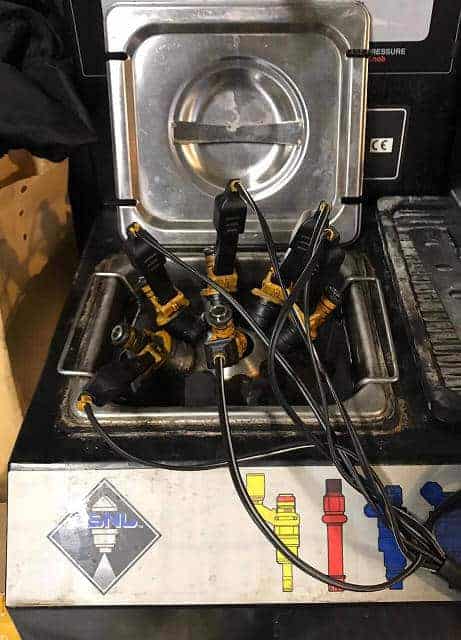
Because the engine was shut down years ago and the fuel present has become stale, it was first decided to clean and test the injectors.
It would of course be great if the engine were to start straight away the very first time it is cranked. Because the engine has been sitting for years with stale fuel, it was questionable whether the injectors would still function properly. It would be a shame if the engine did not start the first time because one or more injectors are not spraying correctly. At that moment you do not know whether the issue lies in the injection timing, the injected quantity, ignition timing, you name it. That is why it was decided to clean the injectors in an ultrasonic bath with cleaning fluid and then test the flow. The image below shows the cleaning procedure. With thanks to Manuel Nunes Pombo and D.F. Krijgsman motorenrevisie B.V.
After cleaning, the injectors were checked in a test setup for the injected quantity (flow) and for leakage when there is no actuation. The videos below show the spray pattern during injection and the leak test.
You can see that one injector does not inject anything at all and other injectors do not have a proper spray pattern. During the leak test, fuel continues to leak from two injectors. Even after cleaning them three times, there was no improvement. If we had not checked this and had attempted a first start, we would have lost a lot of time after the rough running and stalling trying to find possible causes.
Because tuning mainly involves changing the maps related to injection, the fuel supply obviously has to function properly. The ignition system has already been completely renewed – a new coil, ignition leads and spark plugs – so it was decided to also fit six new injectors. The injectors will remain sealed in their packaging for as long as possible; they will be installed in the intake manifold just before the first engine start.
Ignition system:
The original ignition system with distributor ignition is being replaced by an electronically controlled, triple DIS coil with internal drivers. The coil comes from a Volkswagen V6 engine (engine code AQP).
The diagram below shows the pin assignment of the coil (component code N152).
The coil is provided with a control signal by the engine control unit (J220). Instead of the original control unit, the MegaSquirt controller will supply this signal.
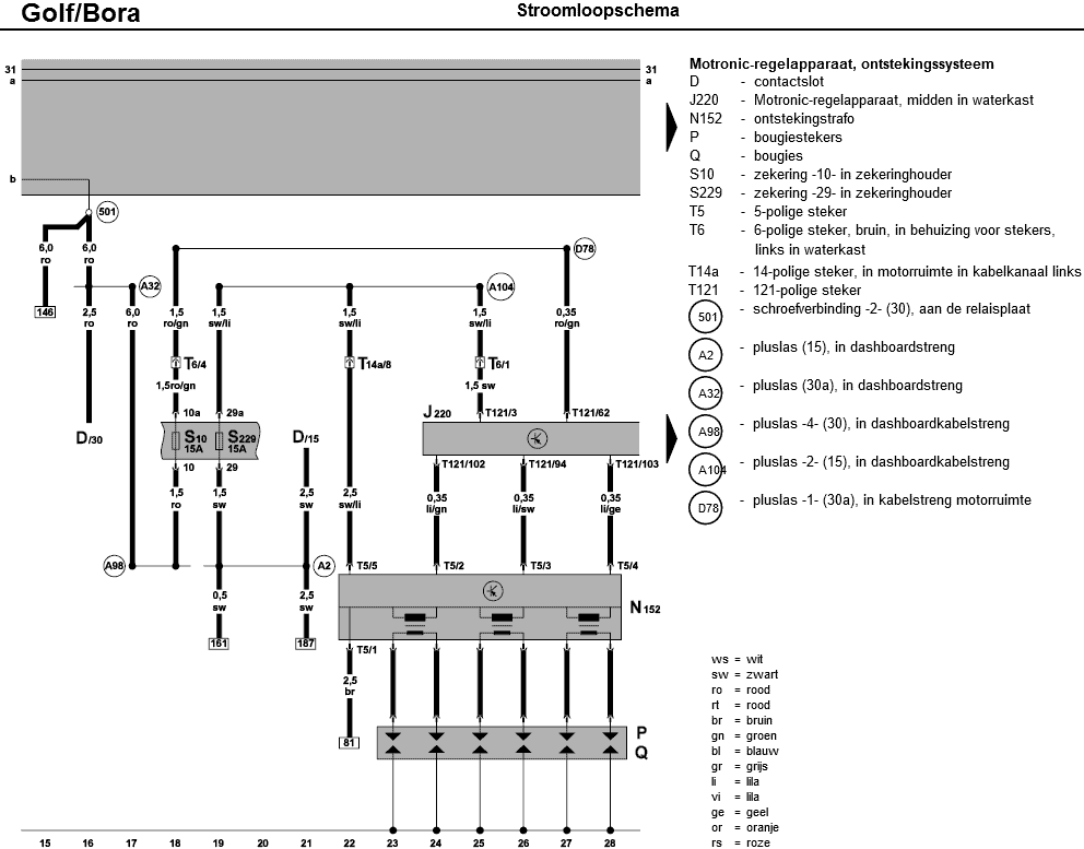
- ground;
- ignition signal spark A (cylinders 1 and 6);
- ignition signal spark B (cylinders 3 and 4);
- ignition signal spark C (cylinders 2 and 5);
- positive (12 volts).
The following properties are also known and can be entered directly into TunerStudio:
- Spark output: going high;
- Number of coils: 3, wasted spark;
- Cranking dwell: 4 ms;
- Nominal dwell: 2.3 ms.
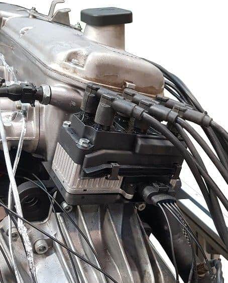
To mount the coil as close to the engine as possible, we fabricated a custom bracket. The bracket is mounted at the bottom to the transmission housing using the gearbox bolts. The coil is attached to the bracket with four M6 bolts and nuts.
Idle control:
A two-wire PWM valve can be connected directly to the MSII ECU. The controller sends a pulse width modulated signal to the PWM valve, which opens against spring pressure. As the duty cycle is reduced or falls away, a spring in the PWM valve pushes the control valve closed. The second connection is for the power supply.
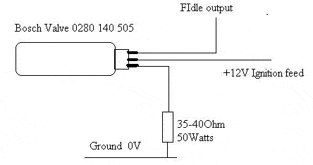
The PWM valve of the BMW engine has three connections:
- PWM for the positive edge;
- PWM for the negative edge;
- Ground.
The MSII ECU sends the PWM signal to the connection for the positive edge. The valve opens, but no longer closes. The internal spring is missing. A negative PWM signal should ensure closing. To make closing possible anyway, in this case a 35 ohm, 50 Watt resistor is installed between the ground connection of the PWM valve and a grounding point on the engine. When using this resistor, a small current always flows through the PWM valve, acting as a kind of “electric spring”. The PWM signal that the controller sends to the valve overcomes the spring force of the small current. When the signal is reduced or drops away, the current pulls the valve closed again.
The 35 ohm resistor becomes very hot and in fact represents a loss of energy. Manufacturers try to minimize these kinds of losses. In this case, apart from looking for another type of PWM valve, we have no other choice. Because the resistor becomes so hot, it will be mounted on the metal of the engine frame. Through this contact, the resistor dissipates its heat.