Topics:
- Assembling the MegaSquirt II ECU
- JimStim simulator
- TunerStudio
- Settings
Assembling the MegaSquirt II ECU:
The MegaSquirt is supplied as a kit. The configuration of the MegaSquirt depends on the engine configuration and the sensors and actuators used. In some cases, the components are not resistant to high current levels. When choosing the ignition driver, consideration must also be given to which type of ignition coil is used. At this stage, a choice must already be made between three different options when assembling the MegaSquirt. In many cases multiple circuits can be installed, but the correct circuit is activated by means of jumpers.
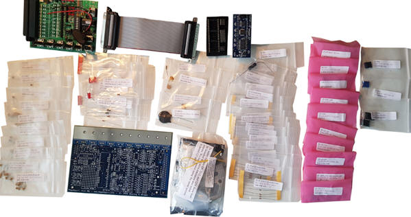
The image shows an overview of the supplied parts. At the top left is the simulator, which can be used after the assembly process to generate and measure the MegaSquirt’s input and output signals. At the bottom in the middle, on the left, the MegaSquirt circuit board can be seen and on the right a bag with large connection components. The daughter board, which also makes it a MegaSquirt 2 version, is visible at the top in the middle. This daughter board is later inserted into the mounted processor socket. Between the clearly visible parts there are fifty bags with loose components. Each bag contains various electrical components, such as resistors, transistors, diodes, op-amps, voltage regulators, LEDs, an opto-coupler and several other ICs.
JimStim simulator:
The simulator used is suitable for configuring the MegaSquirt before it is mounted on an engine. The simulator has a number of hardware circuits with which sensor signals can be generated. Turning the potentiometers results in changing sensor values. On the computer screen, the gauges in the TunerStudio program will display these values (Appendix 29). The sensors that can be simulated are as follows:
- Intake air temperature;
- Coolant temperature;
- Throttle position;
- Lambda value;
- (Spare);
- Crankshaft speed;
- Crankshaft speed (fine adjustment).
In addition to the sensor values, the adjustments of the engine management can also be checked. Changing one sensor value can affect the control of one or more actuators. At the terminals, which act as a breakout box, it is possible to measure the signals using a multimeter or oscilloscope.
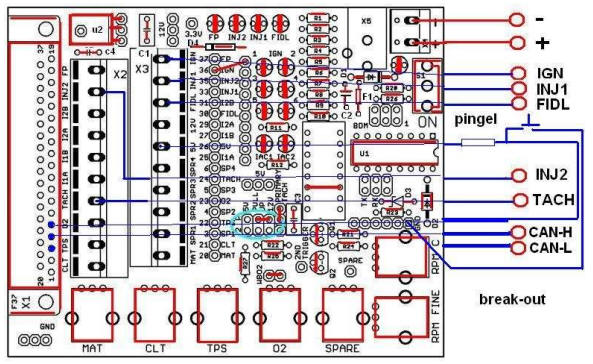
The image shows the assembled JimStim simulator, on which no controllers or jumpers have yet been installed. On the left side you can see the connector where a flat cable makes the connection between the MegaSquirt and the simulator. After the assembly process is completed, the simulator is replaced by the connector on the engine to which all sensors and actuators are connected.
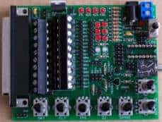
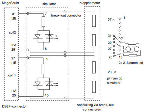
There are several DIP switches on the simulator. These are used to set the crankshaft signal correctly. A schematic overview is shown in Appendix 17. For example, it is possible to choose between a 36-1 or a 60-2 crankshaft reference wheel, between a 5 volt or 12 volt signal, and whether the crankshaft position sensor supplies an AC or DC signal. Naturally, the settings are chosen to match the components as they will be mounted on the engine. The simulator is equipped with several LEDs. These LEDs light up or flash when the following electrical components are controlled:
- Fuel pump;
- Injector control 1;
- Injector control 2;
- Ignition control 1;
- Ignition control 2;
- PWM signal of the idle control valve (if present);
- Stepper motor control (if present).
The JimStim simulator is mounted on a panel of transparent plexiglass. Measurement terminals have been fitted in the plexiglass. The connection between the simulator and the measurement terminals must be made by soldering wires.
TunerStudio:
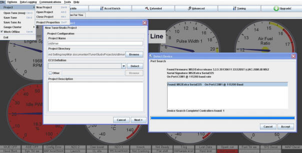
The MegaSquirt II ECU is connected to a desktop PC or laptop using the software program “TunerStudio”. Via this program, settings can be loaded into the MegaSquirt. The image below shows the screen where the MegaSquirt is connected to the PC via a COM port.
The image below shows TunerStudio’s gauges. While operating the potentiometers on the simulator, or while the engine is running, the gauges in this screen display the sensor values and actuator controls.
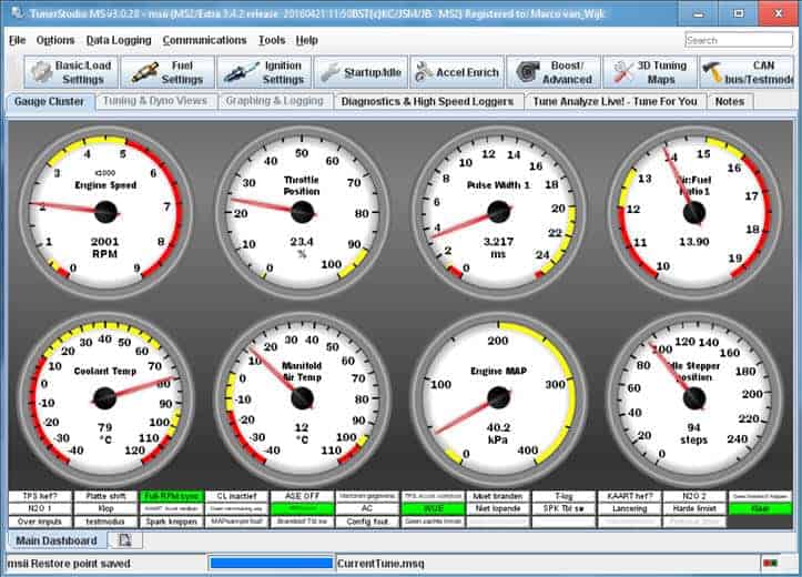
- Engine speed: Crankshaft speed
- Throttle Position: Throttle position, opening angle
- Pulse Width 1: Injector opening time
- Air:Fuel Ratio 1: Actual air / fuel ratio
- Coolant Temp: Coolant temperature
- Manifold Air Temp: Intake air temperature
- Engine MAP: Vacuum in the intake manifold
- Idle Stepper Position: Stepper motor position, number of steps
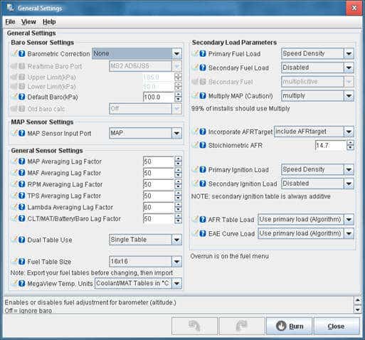
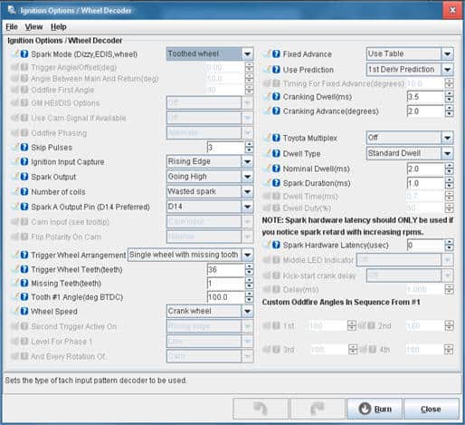
Engine settings in TunerStudio:
The engine characteristics have been entered in the TunerStudio program. The images below show the screens used to make the settings.
Next: Settings