Topics:
- Tuning the engine management system
- VE table
- AFR table
- Ignition advance table and Cold Advance
- Dwell battery correction
- Switching on the ignition and starting, Cranking Pulse
- Idle
- Acceleration
- Priming pulse
- Additional enrichment
Tuning the engine management system:
The previous chapters described how the engine was prepared and which choices were made to shape the engine management system. The implementation chapter explained how the obtained data were processed in the engine management system. Entering all parameters alone is not sufficient to get the engine running. It still needs to be “tuned”, meaning adjustments are made based on measurements and empirical results.
The software-based adjustment of the engine has a major influence on its operation. An incorrect setting can cause rough running, stalling and can even lead to engine damage. The latter can occur with a mixture that is too lean. Injection time and fuel quantity depend on a number of factors:
- Engine speed (RPM);
- Load;
- Temperature.
To ensure good mixture formation at all times under varying operating conditions, the ECU must be properly configured before the first engine start. The settings are made by filling in a number of tables, namely:
- The VE table for volumetric efficiency;
- The AFR table for the air/fuel ratio;
- The ignition table for ignition timing.
The tables are entered in the TunerStudio program. Entering incorrect values may result in the engine not functioning properly, so system knowledge is essential here. The following sections explain how the tables were determined. The base injection time, i.e. without enrichment, is determined through a number of calculations.
The specific mass of the air (ρ) is calculated from the measured temperature of the intake air and the vacuum (the value from the MAP sensor). It should therefore be clear that properly filled tables are necessary for proper engine operation.
VE table:
In the chapter on the injection system it is explained what the VE table is used for. This section explains how the data for the VE table were determined for the Land Rover engine.
In the VE table, each cell indicates the percentage corresponding to the manifold pressure in relation to engine speed. This percentage will be highest at the engine speed where torque is highest. At that point the engine is the most efficient because cylinder filling is best. The torque and power curve of the Land Rover engine is shown in the image below.
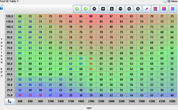
The image shows a VE table filled using a generator. The Y-axis shows the pressure in the intake manifold as registered by the MAP sensor. 100 kPa equals 1 bar (atmospheric pressure) and is the maximum pressure that exists in the intake manifold of a naturally aspirated engine. The X-axis shows the engine speed.
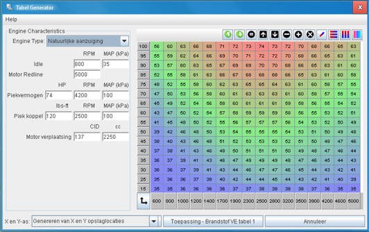
Before starting the engine for the first time, the VE table must be filled in approximately. The final setting of the VE table must be done on a test bench using a wideband lambda sensor and with the lambda control switched off. The “TunerStudio” program, which is used to configure the MegaSquirt with software and parameters, has a helper tool that calculates the values in the VE table. However, the VE values can also be calculated using formulas. The data from the table are used to fill in the formulas.
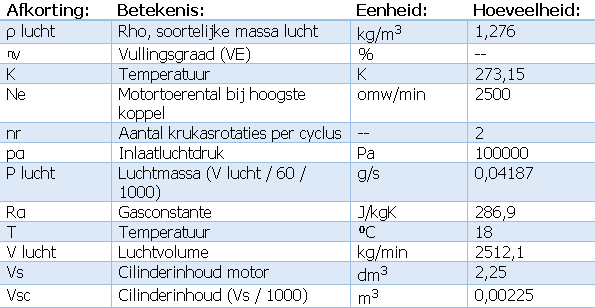
V air is determined under the same conditions as in an earlier calculation; namely at the engine speed where the torque is highest. The answer from a previous calculation is therefore carried over into the following formula.
The (manifold) pressure in the intake manifold and the intake air temperature influence the specific mass of the air, and therefore also the volumetric efficiency formula. With the known and calculated data from table 3 and this formula, the volumetric efficiency can be determined.
In the cell at 2500 RPM and 100 kPa in the VE table, 70% can be entered. This is in the top row of the series of numbers, where the throttle valve is fully open. The calculations can be repeated several times to fill in other values in the VE table. Intermediate cells can be generated using an interpolation function. The computer determines the intermediate values by means of a linear progression. This ensures that the “hill” visible in the 3D display runs as smoothly as possible and that there are no dips and spikes in between. Once the cells in the 100 kPa range between idle and maximum engine speed have been filled in, the torque curve can be derived from this. When, for example, the torque at maximum speed is halved, the VE value will also be half of the maximum value; in this case about 35%. If it is decided to fill in the cells by estimation, the entire VE table can also be filled in this way. The VE table created with the above calculations and reasoning will be good enough to run the engine, but will certainly not yet be correct. The final setting of the VE table must take place on a test bench using a wideband lambda sensor and switched-off lambda control to prevent AFR corrections, where the engine can be loaded for long periods. Because a test bench is not used for this project, the adjustment will be carried out as well as possible in the idle area and at elevated RPM with low load.
Getting a smooth idle is the most difficult part and is done last. It is advisable to keep the engine at an elevated speed (about 2000 RPM) and first let the engine warm up until it reaches operating temperature. Temperature changes then have as little influence as possible on the VE values. After the complete VE table has been corrected, the corrections for lower temperatures (e.g. during a cold start) can be entered. This is possible in the separate configuration menus such as cold start enrichment.
The maximum engine speed is a factor that must be taken into account when filling in the table. With a table of 16 * 16 = 256 cells, it is more accurate for the intermediate engine speeds to limit the maximum speed as much as possible. There is no point in filling the table up to 7000 RPM while the maximum engine speed is 4500 RPM.
While adjusting the approximately filled VE table, the actual lambda value will be used to correct the percentages at the correct manifold pressure (MAP) and engine speed. This value must be brought to λ = 1 by adjusting the VE value. For example, if a ratio of 12.3 is measured while 14.7 is set in the AFR table, the VE value must be lowered until a ratio of 14.7 is measured. Lowering the VE value will inject less fuel. The mixture becomes leaner.
The Innovate wideband lambda sensor with external controller measures the mixture composition and passes this on to the MegaSquirt via a voltage between 0 and 5 volts. The software converts this voltage into an AFR value (e.g. lambda = 1). After measuring and adjusting various cells in the VE table, the intermediate cells can be filled in automatically by interpolation. Adjusting the VE value results in a different injection strategy. The injector control is derived from the value that indicates how much air is present in the engine: in other words, the value in the VE table.
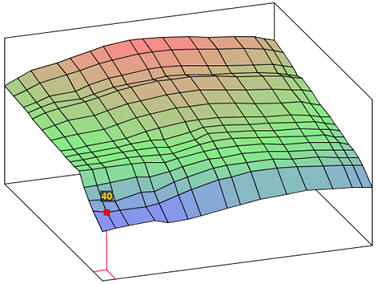
Unfortunately, we did not have a dynamometer and it was not possible to test the engine under load on the road. We are therefore somewhat limited to no-load running. However, there is a brake drum originally intended as a parking brake. This brake can be applied briefly to load the engine. With a gear engaged (for example fourth gear) and the brake applied, the lambda value can be corrected at certain engine speeds. We correct the intermediate values using the interpolation function. Detonation may occur during the test. In an earlier stage the ignition table, containing the ignition advance, was filled in. The desired advance may deviate from the values entered in the table. When slight detonation is heard, the ignition must be advanced a few degrees less (i.e. retarded). About 3 degrees is often sufficient. Of course this can be adjusted again later once the VE table is completed. The VE table values can also be displayed in 3D view. This makes it clear whether there are no large deviations, such as odd points and dips.
Not only can it be checked whether the values calculated by the generator are logical, but the VE table could also be partially filled without using the generator. The engine is most efficient around the speed where the torque is highest: the volumetric efficiency is then highest and the value in the VE table is also highest. After all, the VE table indicates the volumetric efficiency of the engine as a percentage.
After the VE table has been completely filled in, the lambda control can be switched back on.
The images below show the completed VE table and the 3D view with which the Land Rover engine operates correctly.
AFR table:
On the injection system page, the function of the AFR table is described, and why leaning out and enriching are necessary for delivering power and economical driving. This page describes how the AFR table was configured for the Land Rover engine.
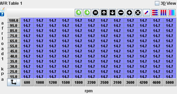
First the VE table is set, only then is the AFR table corrected. However, the AFR table must initially be set entirely to 14.7, so that the MegaSquirt does not apply any correction while the VE table is being configured (see image). Initially, a stoichiometric air/fuel ratio is assumed. The lambda control is also switched off. Only after setting the VE table is the AFR table filled in and the lambda control switched on.
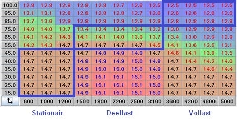
The image shows a filled AFR table, where the air/fuel ratio varies between 12.5 (rich) and 15.1 (lean). When filling in the AFR table, the mixture in the full-load area will be enriched. The enrichment can be seen over the entire area between 75 and 100 kPa. Here the throttle valve is fully open. During part load and around the torque RPM the mixture is lean; the ratio here is 15:1. This can be seen between 1500 and 3100 RPM at a vacuum of 15 to 40 mbar. Here the throttle valve is only partially open. In this area the engine is most efficient.
Ignition advance table and Cold Advance:
On the ignition system page it is described what ignition advance entails.
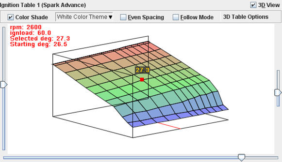
The ignition advance table is set based on the factory data of the centrifugal advance with vacuum control. The black line indicates mechanical advance.
The blue line represents the mapped (3D-ignition) control. To prevent entering the part-load detonation area, a correction is applied; the actual advance follows the red line.
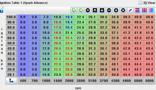
The 3D display shows that there are no deviant values such as dips or peaks. The table should be fairly “smooth” and should not have too many bumps.
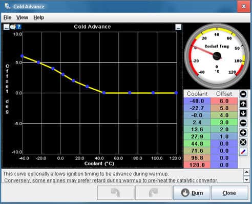
In addition to the standard settings in the ignition table, it is also possible to provide extra advance for a cold engine via “Cold Advance”.
With a cold engine, more advance is required because combustion then proceeds a bit more slowly. To compensate for this delay, the advance is increased by up to 6 degrees. The image shows these settings.
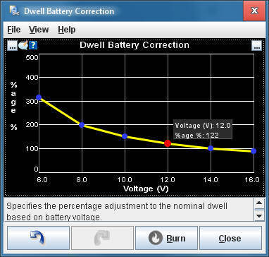
Dwell battery correction:
On the “Actuators” page, in the section about the applied ignition system, it is described what influence battery voltage has on the charging time of the primary ignition coil winding. The image shows the settings screen in which the already calculated corrections have been entered.
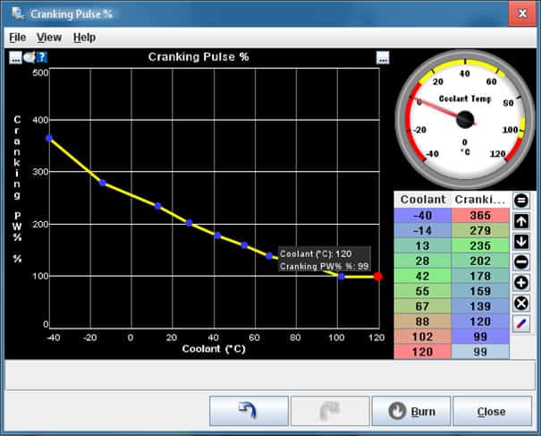
Switching on the ignition and starting, Cranking Pulse:
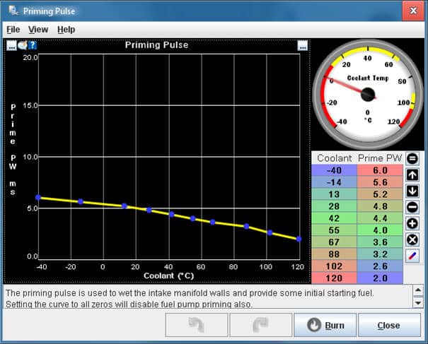
After the ignition is switched on, not only is the fuel pump energized, but the injectors are also actuated once. This is called the “priming pulse”. The fuel injected during the priming pulse condenses on the – likely – cold walls of the intake manifold. The starting process will now proceed more easily because the fuel injected for starting is not lost due to the situation mentioned above. The amount of fuel injected during the priming pulse depends on engine temperature. A warm engine requires a lower priming pulse. The desired amount can be set in a graph in TunerStudio.
The cranking speed is often less than half of the idle speed. The so-called “Cranking Pulse” must be set in the MegaSquirt. Because no throttle is applied during starting and the throttle valve therefore remains closed, the required air must come through the idle control valve. It is possible to set a throttle position at which injection is terminated. In this project, a stepper motor is used. This stepper motor is therefore partially opened during starting. The position depends on the coolant temperature; more air when the engine is cold and less when it is warm. In addition to air supply, injection must also be adapted to the conditions under which the engine is started. The amount of fuel is adjusted by varying the injection time. At a coolant temperature of 25 °C, the injected fuel quantity is doubled compared to a situation where the engine is at operating temperature (around 90 °C). The image shows the curve where the injection quantity can be set relative to coolant temperature. A PWM of 100% is equal to the calculated amount of fuel; anything above that is extra enrichment.
Idle:
The throttle valve must be completely closed during idling. The air supply during idling is controlled entirely by the stepper motor used.
Acceleration:
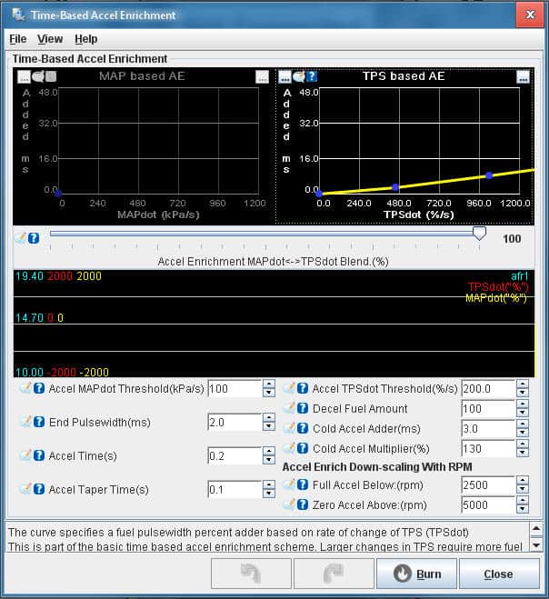
Acceleration requires a richer mixture. The mixture ratio must be adjusted to the speed at which the accelerator pedal is depressed. In the TunerStudio program, the acceleration enrichment is configured using the “Acceleration Enrichment” option, abbreviated to “AE”. Adjusting the acceleration enrichment should only be carried out when the VE table has been correctly filled in.
Because the engine in this project is equipped with both a throttle position sensor and a MAP sensor, both the throttle position and the manifold pressure can be determined. For the change in throttle position, TPS-dot is used. The “dot” indicates the speed of the change and is expressed as a percentage. Depending on this percentage, more fuel is injected. The injection duration is extended by a number of milliseconds. A TPS-dot value of 100% indicates that the throttle valve has moved from closed to fully open in a period of 1 second. If opening occurs even faster, the percentage will increase. It is important to know from which position the throttle is opened; if the engine was already running at part load for some time before acceleration, it cannot be assumed that the throttle was fully closed. The position in which the throttle is located is indicated as an acceleration threshold, or “threshold”. The threshold indicates the throttle position from which it is considered to have moved to fully open throttle. The acceleration taper indicates the transition time from the acceleration injection time to the end of the enrichment. This prevents the acceleration enrichment from ending too quickly.
The initial setting of the acceleration enrichment can be checked using the simulator. Final adjustment must be determined empirically, with or without the help of the wideband lambda sensor.
Priming pulse:
The priming pulse is a function that injects a small amount of fuel onto the intake valves when the ignition is switched on. This facilitates the starting process. With a warm engine, the injected amount decreases. The priming pulse is adjusted with the blue points in the curve (see image).
Additional enrichment:
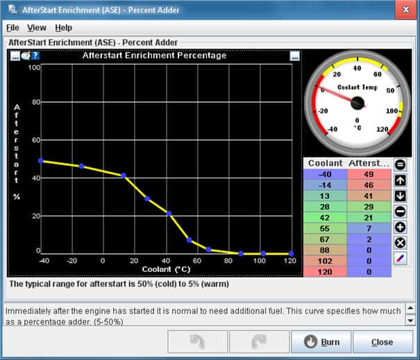
Immediately after the engine fires following starting, an enrichment is applied. This is called “AfterStart Enrichment”. The MAP is still too high because the engine speed is not yet high enough to create sufficient vacuum. Especially with a cold engine, enrichment is applied for a certain time until the engine starts running according to the VE settings.
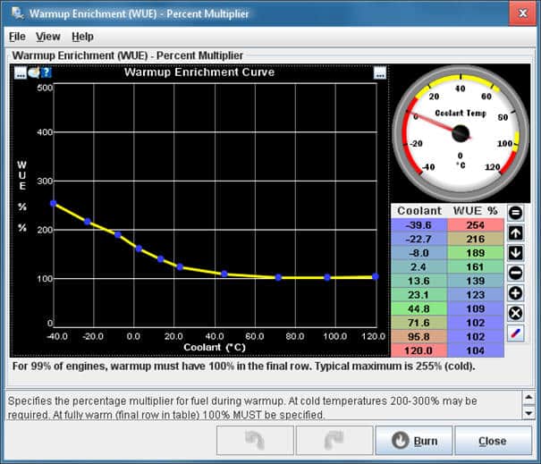
The “Warmup Enrichment” (WUE) provides enrichment during the engine warm-up phase. When the engine approaches its operating temperature, the enrichment must be 0%.
Next: Testing.