Topics:
- The start of the project
- Engine
- Gearbox
- Inspecting, replacing and adjusting engine components
- Mounting the engine on a mobile frame
- Cooling
- Dashboard and electrical installation
- Fuel pump and tank
- Operating the engine in the classic configuration
The start of the project:
After the decision was made to equip an engine with a MegaSquirt engine management system, a suitable engine type was considered. Standard conversion kits with manuals were not of interest. The objective was to use an engine that met the following conditions:
- there must be no known previous conversion projects for this engine;
- four-cylinder petrol engine;
- not yet equipped with an injection and electronic ignition system;
- the possibility to load the engine.
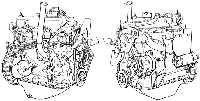
Engine:
The search led to an engine from a Land Rover (series 2A) from the early 1970s. This 2.25 litre four-cylinder petrol engine with three main bearings was originally equipped with a carburettor and mechanical distributor ignition. The combination of this Land Rover engine and the original gearbox was decisive in the choice; a transmission brake is mounted on the output shaft of the gearbox. The transmission brake, which actually serves as a parking brake, makes it possible to load the engine while it is running by applying this brake.
The engine had probably not run for decades. Naturally, it must be reliable enough to run on the engine management system. It was therefore necessary to thoroughly inspect and test the engine first. The following objectives were defined:
- Inspect, replace and adjust engine components;
- Mount the engine on a mobile frame;
- Operate the engine in the classic configuration;
- Install components for the engine management system;
- Assemble and prepare the MegaSquirt ECU;
- Run the engine on the engine management system.

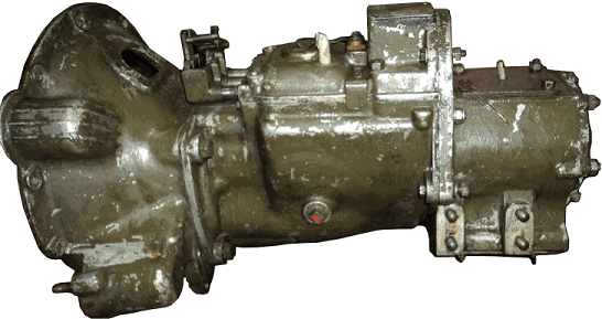
Gearbox:
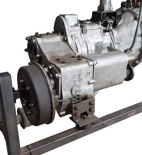
The gearbox comes from a Land Rover previously used by the army. The green colour actually already gives it away. To later form a whole as original as possible with the engine, the green paint was removed. The transmission brake is not yet present in the photo; it was later mounted on the output shaft in accordance with the factory specifications.
Inspecting, replacing and adjusting engine components:
At the start of the project it was unclear whether the available engine was suitable for use. Little was known about the engine block, other than that the engine had stood still for many years. It was unclear whether internal components were damaged or even – possibly irreparably – defective. In the latter case, replacing the engine with another unit would be the only way to continue the project.
To avoid discovering at a later stage that the engine would be unusable, it was decided to dismantle and overhaul the engine. Wear patterns on the components were checked and compared with factory specifications. Parts whose measurements were within these tolerances were reinstalled. Parts that failed inspection were replaced. The intended purpose of the engine was taken into account; the engine must be built up with as little cost as possible while being sufficiently reliable for carrying out the project and for use as an educational teaching aid.
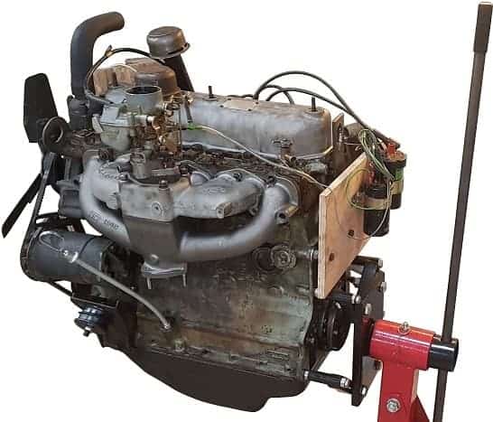
The engine was mounted to the engine stand at the mounting points of the gearbox housing. The engine can be rotated into various positions. This provides optimal access to both the cylinder head and the oil pan for disassembly work. For the engine to function properly it is important to take precautions to ensure good final compression pressure. If the pressure in one or more cylinders is too low, this results in a poorly running, stuttering engine. In that case, adjusting the new ignition and injection system is difficult or even impossible.
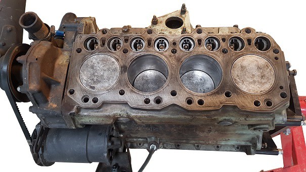
One of the first inspection points are the pistons and cylinder walls. For a proper inspection, the pistons had to be removed from the engine block. After removing the cylinder head and oil pan, the pistons could be taken out. The pistons were checked for ovality and visible signs of wear. The piston rings were also checked for wear. Worn piston rings can cause compression loss and oil consumption; both of these consequences must be prevented by this inspection. In addition to a visual inspection, the clearance between the piston ring grooves and the piston ring was measured.
The image below shows a measurement in which the piston is measured with a micrometer. In addition to ovality, the clearance between the piston and the cylinder wall can also be determined. Excessive clearance means there is excessive wear. For the project this would mean that oversize pistons might have to be fitted. After the four pistons had been assessed both visually and geometrically, it could be concluded that there was no excessive wear.
After replacing piston rings, the ring end gap must be measured and, if necessary, adjusted in order, on the one hand, to prevent the piston ring from breaking (as a result of too little or too much clearance) and, on the other, to reduce compression losses (leakage losses due to excessive clearance). The piston ring is placed in the cylinder where the diameter is smallest. The ring end gap is measured with a feeler gauge. This measurement is shown in the image. The piston rings of cylinder 1 were replaced because of their poor condition and had to be filed one millimetre smaller; in the installed state the ends were touching.
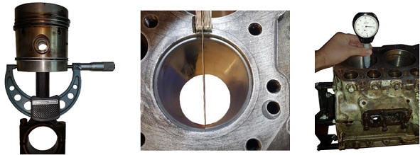
The wear of the cylinder liners is measured using a suitable measuring tool. The movement of the gauge needle shows the degree of wear. The image shows the cylinder measurement of cylinder 4. The cylinder diameter will have increased mainly on the side where the thrust force occurs. The cylinder walls may show some wear, but the wear must remain within tolerances. The measurement results showed that wear on the cylinder walls was within allowable limits. A visual inspection of the cylinder liners showed that some areas of the walls were smooth. The honing marks were barely or no longer present.
The honing marks, a kind of small scratches, ensure that there is always a thin oil film between the piston ring and the cylinder wall. The main task of this oil film is lubrication, but it also serves as a seal and thus helps in achieving the final compression pressure. Using a suitable honing stone, new honing marks were applied in all four cylinder liners. The image shows this operation. An attempt was made to apply the honing marks as much as possible in a crosshatch pattern at an angle of 45 degrees.
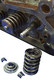
The valves seal the combustion chamber above the piston. Leakage along the valve seat causes compression loss; something that must be prevented. To be able to check the condition of the valves and valve seats, all valves must first be removed from the cylinder head. The image shows a removed valve spring of the inlet valve of cylinder 1. The valve heads of the valves of cylinder 1 were so badly affected that it was decided to replace both.
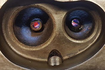
After disassembly, several valve seats turned out to be pitted / damaged. The image below shows the valve seats of cylinder 1. It is highly likely that the engine would not have run properly if this had not been checked. Simply lapping in the new valves would be insufficient, so it was decided to machine the valve seats.
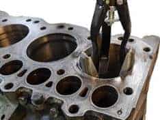
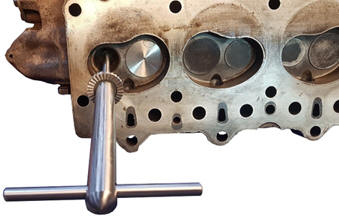
With a valve seat cutter, a small amount of material is removed so that the valve seat is smooth again. The shaft of the cutter is inserted into the valve guide (see image below). This ensures that the cutter can be placed squarely on the seat. During the machining process, two different angles had to be taken into account. The valves of cylinders 1 and 2 were the most affected. For completeness, all eight valve seats were machined. After machining, the valves were lapped in with a special abrasive compound to ensure the best possible seal.
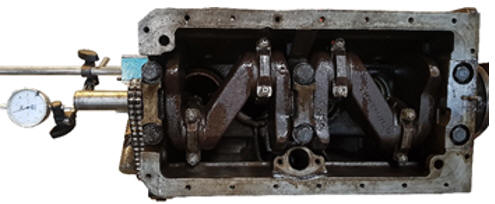
A dial gauge is used to measure the axial crankshaft play of the crankshaft with three main bearings and two thrust bearings. If there is too much axial play and there is no mechanical defect, a larger-size thrust bearing can be installed. The measurement shown in the image indicated that the axial clearance was within specification.
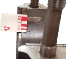
The clearance between the plain bearings of the crankshaft and connecting rod, in other words: the radial crankshaft play, is measured with plastigage (see image). Plastigage is a special plastic thread that permanently deforms after being compressed. After installing the bearing cap or connecting rod, the plastigage leaves an imprint. The width of the imprint indicates how much clearance there is between the bearing and the crankshaft.
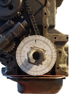
The timing chain transfers the movement of the crankshaft to the camshaft. After installing the pistons, crankshaft and cylinder head, the timing chain must be adjusted again after fastening. Because adjustment and timing marks were missing, the timing had to be determined using the asymmetrical valve timing diagram. With the aid of a degree wheel on the crankshaft it can be determined at which angle the inlet and exhaust valves open and close (see image). The timing components such as the gears, chain, guide and tensioner were visually checked for wear. They were in good condition.
All components were tightened according to the specified torque settings. Because the engine has been dismantled, checks must be carried out after a number of operating hours. However, this is not possible because the engine will not be installed in a vehicle. It was therefore decided to carry out the checks prescribed by Land Rover after 24 running hours.
Mounting the engine on a mobile frame:
The aim was to use the engine as an educational teaching aid, running on an engine management system. The engine will not be installed in a car. To ensure a safe and reliable setup, it was decided to place the engine on a suitable engine frame. The intention is to mount the engine to the frame at the original engine mount locations. Because there are no off-the-shelf conversion kits, the mounts had to be custom made.
In the build phase a choice had to be made as to how the engine would be configured. The engine management system must be adjusted under increased engine load. Because the original gearbox has a transmission brake, it was decided to also mount the gearbox on the engine frame. By operating this transmission brake, it is possible to run the engine under load for short periods.
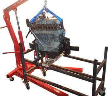
Modifying and adapting the existing engine mounts made it possible to connect the engine to the frame in a reliable way. The engine frame also provides the option to mount a dashboard, on which, among other things, the controls can be installed. The image shows the moment when the engine is hanging above the frame and ready to be mounted.
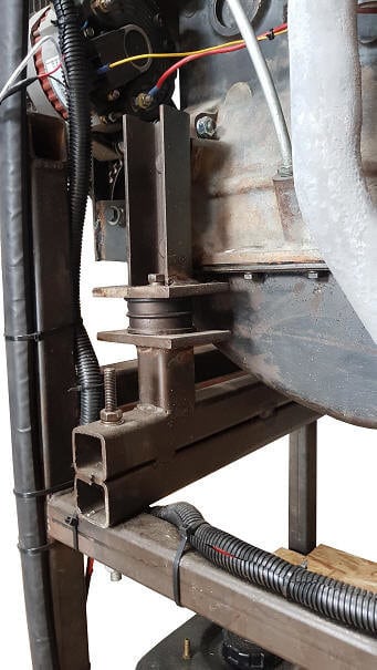
The engine mounts on the timing side are made from steel tubes and U-profiles. An engine rubber provides damping. At the bottom, two tubes are mounted on top of each other to mount the combination of engine block and gearbox on the frame as horizontally as possible. Using M8 and M12 threaded rods, bolts and nuts, the mounts are attached to the engine block and the frame.
On both sides of the gearbox a similar gearbox mount was made on which it rests on the frame.
After the engine and gearbox had been safely and securely mounted on the frame, the build of the engine could be continued. After installing adjustable components, such as the carburettor and ignition, these were set according to the factory values.
Other components required for the operation of the engine were also mounted on the frame, such as the radiator, the dashboard with controls and the fuel tank. These components are described in the following sections.
Cooling:
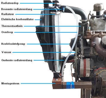
In its original form, cooling is provided by a large radiator and a metal cooling fan mounted on the water pump. Because the engine is not installed in a vehicle but on a mobile frame, it is important to use suitable aftermarket components. The metal cooling fan was replaced by an electrically driven cooling fan with plastic blades. The plastic version is not only much safer as the engine is being prepared for educational purposes (consider personal safety when taking measurements), but is also more suitable for warming up the radiator and engine block more quickly. The electric cooling fan can be switched on and off with a button on the dashboard. This makes it possible to warm up the engine quickly, as there is little possibility to load it mechanically. With a warmed-up engine, a “closed loop” condition is reached sooner, in which the data from the lambda sensor are used to control fuel injection. With a cold engine – in “open loop” – for example, extra enrichment is used: when injecting a larger amount of fuel ( λ < 1) correction of the fuel mixture by the lambda sensor is undesirable.
The image shows an overview of the components of the installed cooling system. The original radiator was not available. Because its size and weight were not suitable for mounting on the engine frame, a smaller aftermarket radiator was chosen. The diameters of the connections for the upper and lower radiator hoses correspond to the original ones.
The upper and lower radiator hoses were custom-made using silicone hoses and connectors. The electric cooling fan is mounted on a bracket. The upper radiator hose protects the radiator from tipping. With a pressure cap (0.9 bar), the cooling system is protected against excessive pressure. When the pressure becomes too high, the valve in the radiator cap opens against the spring force and coolant flows through the overflow into a catch tank.
By trial and error it had to be determined whether the radiator had sufficient flow capacity and whether the cooling fan had enough capacity to dissipate the heat. During the first test phase, the system was found to be in order.
Dashboard and electrical installation:
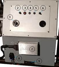
A dashboard is mounted on the frame, containing warning lights, switches, the MegaSquirt ECU, various relays and wiring looms. The dashboard is used to monitor and control the engine functions.
The image shows the dashboard. Number 1 in the figure indicates the position of the master switch; a key interrupts the connection to the battery negative terminal. Because it is not necessary to power the engine when it is switched off, it is safer to disconnect the negative terminal when the engine is left unattended. Number 2 indicates the switch for the cooling fan. Numbers 3 and 4 are the warning lights for the alternator (D+), number 5 is the start button and number 6 is the ignition switch (terminal 15). A fuse box is located at the rear of the dashboard. The MegaSquirt is mounted on the lower panel and indicated by number 7. Number 8 indicates the fuel pump relay. The dashboard also provides the option to mount a breakout box on which students can take measurements. This makes it possible to measure sensor values and actuator control signals with the oscilloscope.
The original starter relay controls the starter motor; pressing a small start button connects pin 86 to ground, allowing a control current to flow. The control current generates a magnetic field, which causes a main current to flow between terminals 30 and 87; the starter motor is supplied with this main current until the start button is released.
The retrofitted alternator provides the charging voltage and current to the battery. A warning light indicates whether the alternator is charging correctly. The lambda sensor, injectors and ignition coil receive supply voltage from the fuse box. Other signal and ground wires provide the data transfer and the on/off commands from the MegaSquirt.
Fuel pump and tank.
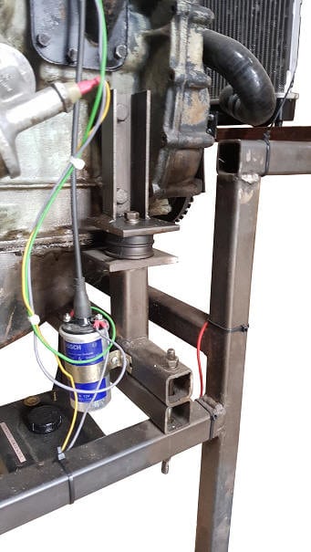
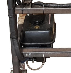
In the classic configuration, the mechanical fuel pump is no longer used when installing the engine management components, because its working pressure is too low (200 mbar). The required fuel pressure for MPI injectors controlled by the MegaSquirt ECU is 3 bar. A standard electric fuel pump from a passenger car is sufficient. Due to the limited space, a compact unit was chosen in which the fuel tank, pump and filter are housed in a single casing. A metal frame makes it possible to mount the unit to the engine frame. At a later stage of the project, the fuel hoses will be installed to connect the fuel pump to the injectors in the intake manifold.
The power wires for the fuel pump run through a cable duct to the instrument panel, the installation of which has already been described. The positive wire of the pump is energised via a relay by the MegaSquirt.
Operating the engine in the classic configuration.
Before installing the components for the engine management system, the engine was first made operational in the classic configuration, i.e. with carburettor and distributor ignition. Chapter 5.2 describes the work that was carried out to mount the engine and auxiliary components on the engine frame. In the first test phase, during which the engine was started in the classic configuration, checks could be carried out under the following conditions:
- Cold start;
- Idling;
- Increased engine speed, increased load;
- Extended running at operating temperature.
During the above checks it became apparent that several repairs were still required before the engine was reliable enough for the conversion.
- After the first engine start, it turned out that the seal in the coolant pump was no longer in order; coolant was leaking from the engine block along the bearing. Replacing the coolant pump was sufficient to solve the problem.
- A subsequent problem was stalling when the engine reached operating temperature. The ignition failed, preventing the engine from being restarted. The problem was located in the distributor and was easy to fix.
- After some time, an oil leak developed between the engine and the gearbox. The leak is presumably coming from the crankshaft seal. This leak will be repaired after the project has been completed.
After the engine in the classic configuration was found to be in order, work on the electronics could continue.
Next: Sensors.