Introduction:
The steering system of a car is very complex. Steering movements must be correctly transmitted to the road surface, without play and without heavy spots while steering. This page explains which types of steering systems exist and how power steering is applied to the steering gear. The operation of the power steering is described on the power steering page.
Steering column:
The image below shows the complete steering system of a car. The section between the steering wheel and the flexible rubber boot is mounted in the dashboard. This is usually covered with plastic trims and is not visible. The steering movements are transmitted via the steering column to the steering shaft. The steering shaft is mounted to the steering gear; this is explained further down this page.
Often it is not possible to use a straight shaft between the steering wheel and the steering column, and one or more bends are needed. This can also be seen in the image below. At the flexible rubber boot there is a universal joint fitted, which makes it possible to transmit the steering movements at an angle from the steering column to the steering shaft. The purpose of the flexible rubber boot is to seal the opening in the bulkhead where the steering column or steering shaft passes from the interior to the engine bay. The boot ensures that engine noise and heat cannot escape from the engine bay into the interior. When squeaking noises are heard while steering, it may be that the steering shaft is squeaking in the boot. Applying a small amount of lubricant can possibly solve this.
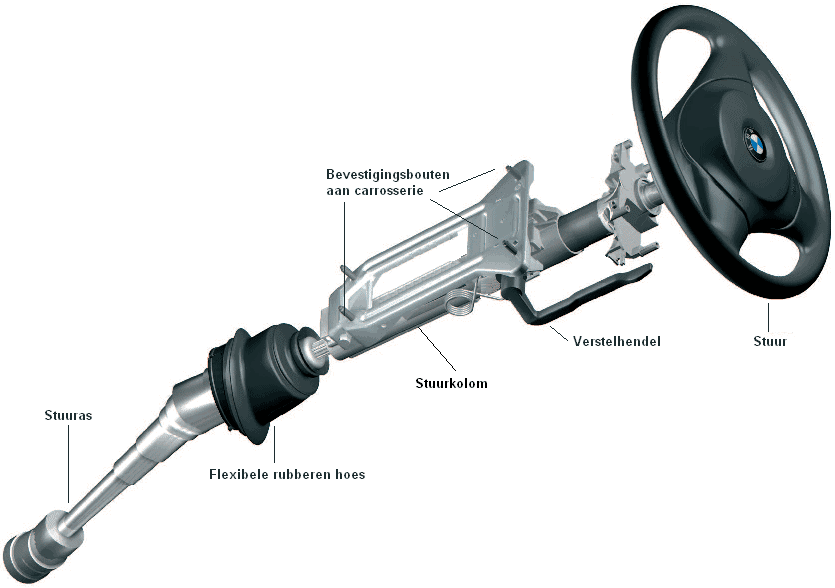
The steering column in the image above is adjustable. By unlocking the adjustment lever, the complete steering column (depending on the version of the car) can be moved up and down, pushed in and pulled out. The latter is possible because a large part of the steering shaft consists of two shafts mounted over each other, which can therefore slide in the longitudinal direction. In the steering column in the image, this takes place in the section between the adjustment lever and the flexible rubber boot. The lower end of the steering shaft is connected to the steering gear. This is clarified further on this page.
Direct steering gear:
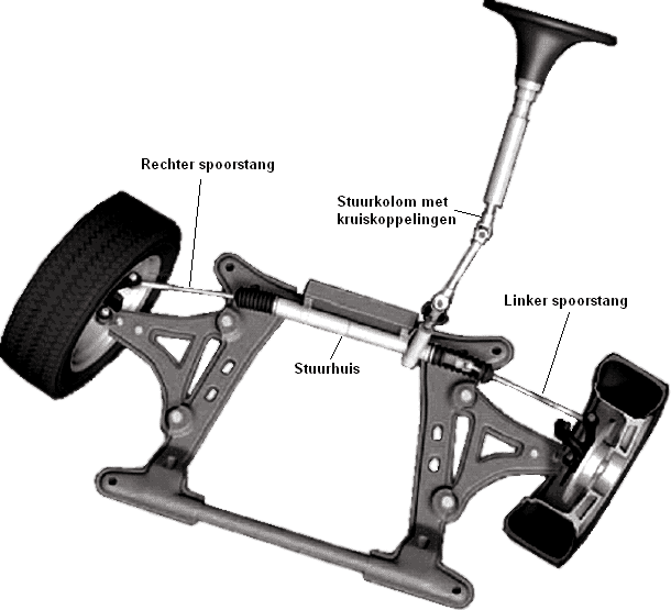
The image shows a direct steering gear. The steering column drives the steering shaft by means of two universal joints. The steering shaft is connected to the rack of the steering gear; here, the rotary movement of the steering shaft is converted into a back-and-forth movement to the tie rods. The steering gear is mounted on the subframe. The tie rods push against the ends of the steering knuckles of the suspension. Because the pivot points of the steering knuckles are located in the middle, a rotational movement takes place. This movement turns the wheels.
The image shows the connection between the rack and the steering gear. At “Mounting point shaft from steering column” a metal clamp fits over this shaft. This clamp is attached to the steering shaft with a bolt in the bolt hole. Because there is a single recess, the steering shaft can only be mounted in one position. Make sure that the steering wheel has not been rotated a full revolution during assembly, as this will break the clockspring of the steering airbag.
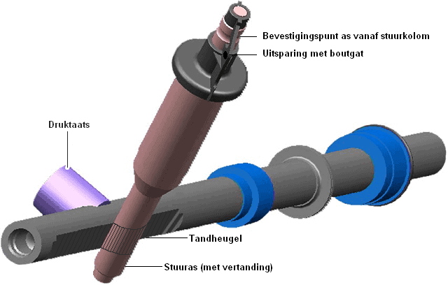
When the steering wheel is turned left or right, the steering shaft rotates over the rack in the steering gear. The steering shaft remains in a fixed position and the rack moves from left to right. This 90-degree transmission ensures that the wheels can be turned from left to right. In the image below at “Connection of the steering shaft” the shaft with rack from the previous image is shown as it is in reality.
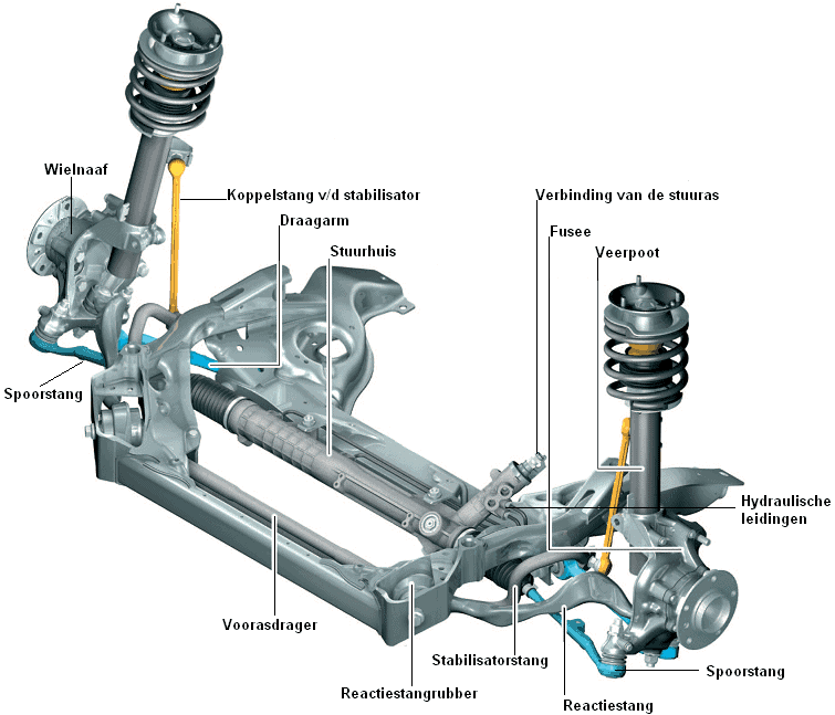
On the steering gear (in the image above, below the connection of the steering shaft) two hydraulic lines can be seen. These lines are for the power steering. There is a constant oil pressure in these lines, supplied by a plunger pump (the power steering pump, also called the servo pump). This pressure is applied to both sides of the steering gear and ensures that the steering movements are assisted.
More about this on the power steering page.
Indirect steering gear:
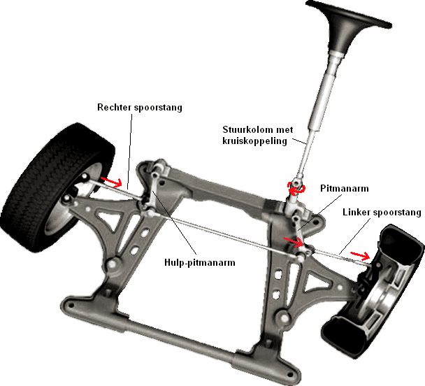
An indirect steering gear is equipped with a pitman arm and an idler arm. A center link is mounted between these arms, which transmits the steering movements from the pitman arm to the idler arm. The indirect steering gear is mounted on the subframe. The image shows an indirect steering gear.
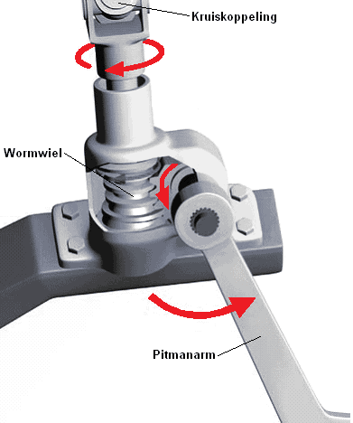
In contrast to the direct steering gear, the steering movements are not transmitted to the rack via the steering shaft, but via a worm gear to the pitman arm. When steering, the worm gear rotates, causing the gear on the pitman arm shaft to rotate along with it. This causes the pitman arm to move.
In the image below, the steering movement is indicated by arrows.
Variable steering ratio:
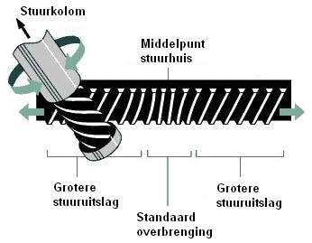
A steering gear can be equipped with a variable steering ratio. When the steering wheel is in the straight-ahead position, the teeth are located close together. Steering wheel movements then cause only a small steering movement of the wheels. This is very pleasant when driving straight ahead, because the driver does not have to correct much.
When the steering wheel is turned further, the teeth that are farther apart are reached. As a result, the same steering wheel movement will cause a larger steering movement of the wheels. This makes, among other things, parking easier, because the steering wheel then needs to be turned less far to reach the maximum steering lock.
Related pages: