Thermistor:
A thermistor is the name for a component whose resistance value depends on temperature. The English word is a combination of the words thermal and resistor. Thermistors are used in automotive engineering, among other things, as temperature sensors and overload protections.
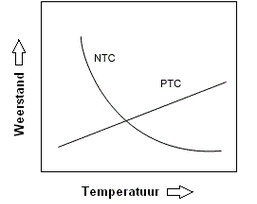
Thermistors can be divided into 2 groups; namely that the resistance value increases with an increasing temperature (PTC) or that the resistance value decreases with increasing temperature (NTC). The terms NTC and PTC are explained in more detail below.
PTC resistor:
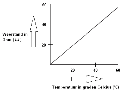
A PTC resistor is a resistor with a Positive Temperature Coefficient. They are mainly used as temperature protection in electrical devices. When the temperature increases, the resistance also increases. The ratio between resistance and temperature has a linear relationship with a PTC resistor. That means that the resistance rises proportionally with the temperature increase. This can be seen as the perfectly straight line in the image below.
PTC resistors are used, among other things, in mirror heating. Without this protective resistor, after switching on there would be a constant (maximum) voltage of 12 volts and a current of 1.25 amperes on the heating elements. In the long run these would burn out, because the supplied current continues to cause heating. By adding a PTC resistor in the positive wire, overloading can be prevented. This resistor monitors the temperature of the heating element. When the mirror heating is switched on during the winter period, the PTC resistor will not function at first yet. The temperature is then too low. The full 12 V / 1.25 A now flows through the heating elements, causing the mirror glass to heat up quickly at first. (The moisture will then disappear from the mirror glass as quickly as possible).
As the temperature rises, the resistance increases (see the image below). When the mirror glass has reached a temperature of 20 degrees, the PTC will have a resistance value of 20 ohms. The current has now decreased from 1.25 A to 0.6 A. This can be calculated using Ohm’s Law:
I = U / R
I = 12 / 20
I = 0.6 A
The current is now therefore halved, which results in a slower heating of the mirror glass. When the temperature of the glass rises to 40 degrees, the PTC has a resistance value of 40 ohms. The current has now dropped to 0.3 A.
At a maximum temperature of 60 degrees Celsius, the resistance of the PTC resistor will be 60 ohms. The current is now only 0.18 A. The heating power is now constant and will not increase further due to the low current. The temperature of the mirror glass therefore also remains constant and cannot overheat. The above values are made up and serve purely as an example to make it as clear as possible. Each manufacturer will use their own current levels (and therefore resistance values) for their mirror heating.
There are also other components in the car that have a PTC resistor, such as a window motor. If the window mechanism runs with great resistance (due to a high mechanical load) or the window is opened and closed many times in succession, the temperature of the window motor increases. This electric motor is also monitored by a PTC resistor. When the temperature becomes too high, this signal is sent via the PTC resistor to a control unit. This temporarily switches off the power supply to the motor until the temperature has dropped. This is purely a safety measure to prevent overheating.
NTC resistor:
An NTC resistor is a resistor with a Negative Temperature Coefficient. These resistors are used as temperature sensors for, among other things, the coolant and the intake air. When the temperature increases, the resistance decreases (see image). A constant voltage between 1 and 5 volts is often applied to the sensor. At a low temperature the resistance value will be high, so the voltage will be low. As the temperature rises, the resistance falls and the voltage increases.
The increase in voltage is used by the control unit for the maps which, among other things, determine the injection quantity of the injectors. The value can also be passed on to the coolant temperature gauge on the dashboard, or the outside air temperature in the climate control display.
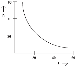
The ratio between resistance and temperature does not have a linear relationship with an NTC resistor. That means that the resistance does not decrease proportionally with the temperature increase. This can be seen in the image as the curved line. This line is called a “characteristic” and follows a logarithmic course.
Determining the NTC characteristic:
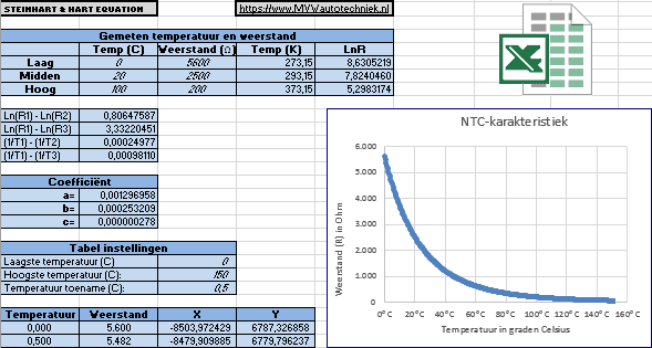
The NTC characteristic can be partly plotted by determining the corresponding resistance value at three temperatures. To do this, the temperature sensor can be measured with an ohmmeter while it is hanging in a heating kettle of water.
At different temperatures and resistance values, points can be plotted. Lines can be drawn between these points (see the image below). With this it is already possible to get a fairly good estimate of how the characteristic will look below 20 and above 100 degrees Celsius.
It is interesting to look into this in more detail. With the three measured resistance values, the exact resistance can be determined over an infinitely large temperature range by means of the “Steinhart-Hart equation”. The characteristic can also be determined accurately. At the bottom of this page an Excel file can be downloaded with which the characteristic can be generated.
The Steinhart-Hart equation is:
- T is the temperature in Kelvin;
- R is the resistance at T in ohms;
- A, B and C are the Steinhart-Hart coefficients which depend on the resistance values at a given temperature.
To find the resistance of a semiconductor at a given temperature, the inverse (R) of the Steinhart-Hart equation must be used. This equation is as follows:
where x and y are determined using the following formulas:
To find the A, B and C coefficients of the Steinhart-Hart equation, three resistance values (R1, R2 and R3) at a temperature (T1, T2 and T3) must be determined. These should be looked up in the semiconductor specifications or measured with a thermometer and an ohmmeter. L1, L2 and R3 are calculated by determining the inverse of the resistance values. Y1, Y2 and Y3 are determined by calculating the temperature in Kelvin to the power of -1.
The Steinhart-Hart coefficients (A, B and C) can then be calculated:
Filling in these coefficients and the ln (R) gives the correct temperature. When the above formulas are filled in, this yields:

Entering all data into the Steinhart-Hart equation:
gives:
The variable “T” can be changed to the desired temperature. The calculation will show that at a T of 120 degrees Celsius the resistance is 122 ohms.
The formula can be filled in with the three previously measured temperatures, with which the characteristic can be plotted:
- 2500 ohms at 20°C;
- 626 ohms at 60°C;
- 200 ohms at 100°C.
Related page: