Introduction:
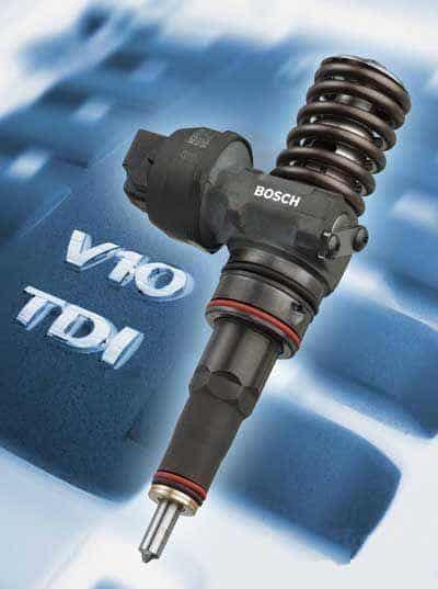
Modern diesel engines are facing ever more demands. Consumers demand more and more comfort and power, while the government and other bodies impose increasingly strict environmental requirements. Car manufacturers are forced to develop cleaner and more economical engines that must also deliver more power. Examples of this are the common rail and the unit injector fuel injection systems. The unit injector injection system was developed by Volkswagen.
Volkswagen used the unit injector technology for the:
- 1.2 TDI,
- 1.4 TDI,
- 1.9 SDI,
- 1.9 TDI 105, 110, 115, 130 and 150 hp,
- 2.0 TDI,
- 2.0 SDI,
- 2.5 R5 TDI,
- 5.0 V10 TDI.
Because of emission requirements, unit injectors are no longer used on new cars, but common rail is.
Operation:
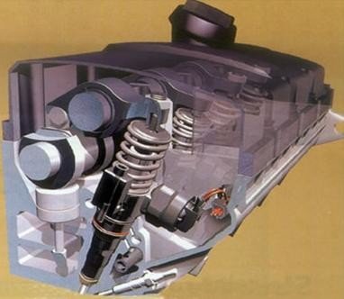
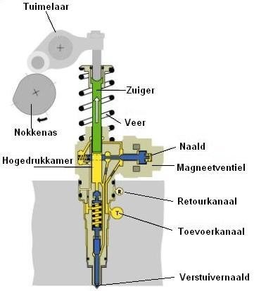
The unit injector injection system is a direct fuel injection system. An electronic fuel pump pumps the diesel fuel from the tank to the fuel supply of the unit injectors at a pressure of approximately 7.5 bar. With this pressure, the pump element is filled. The pump element of the unit injector is operated by the camshaft via a rocker arm. The pressure build-up in the pump element starts at the moment the rocker arm pushes the injector needle down. The quantity of injected fuel is controlled by the solenoid valve; the longer the control unit actuates the solenoid valve, the more fuel is injected.
With the unit injector, multiple injections can be performed in succession can be performed:
- Pilot injection: The solenoid valve starts to be actuated. By using a pilot injection, the combustion starts more gently, reducing diesel knock. The lift of the injector needle during pilot injection is 1/3 of the maximum lift. The opening pressure of the injectors is then 180 bar.
- Main injection: The opening pressure of the injector for the main injection can rise to around 2000 bar. This pressure is reached when the engine is delivering its maximum power. The main injection ends when the solenoid valve stops being actuated.
The rocker arms that operate the plungers in the unit injectors are driven by the camshaft. During the pumping stroke, a high fuel pressure is built up in the high-pressure chamber. The pressure at the top and bottom of the injector needle is equal. As a result, the injector needle remains closed.
When the solenoid valve is actuated, the pressure at the bottom of the injector needle disappears. The pressure at the top is greater, causing the plunger needle to be pushed down.
The fuel that is supplied to the injector but not used for injection is routed back to the tank via the return channel.
Replacing and adjusting unit injectors:
After removal or replacement of a unit injector, it must be adjusted. This is done on the basis of two measurements.
- The first measurement that must be carried out is to install the unit injector straight in the cylinder head. A vernier caliper is used for this.
- The second measurement is to set the maximum stroke that the plunger in the unit injector makes.
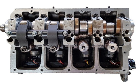
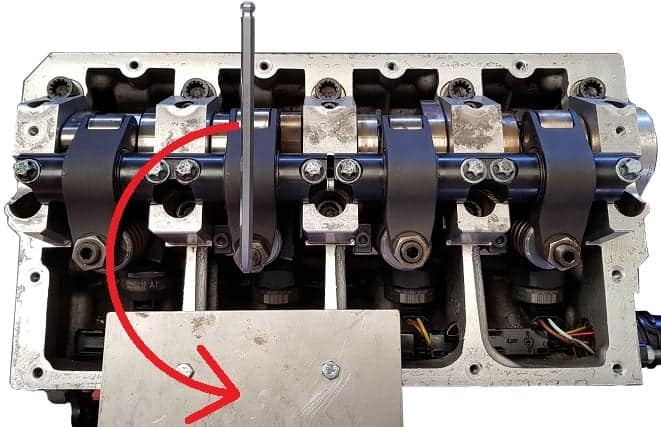
1. Removing the rocker arm shaft.
To replace a unit injector, one of the two rocker arm shafts must be removed. In this case, the rocker arm shaft for the unit injectors of cylinders 3 and 4 has been removed.
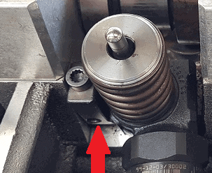
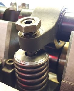
2. Remove the clamping block.
To remove the clamping block, the bolt (indicated with a red arrow) must be loosened. The clamping block is hooked into the injector and must be slid out from between them.
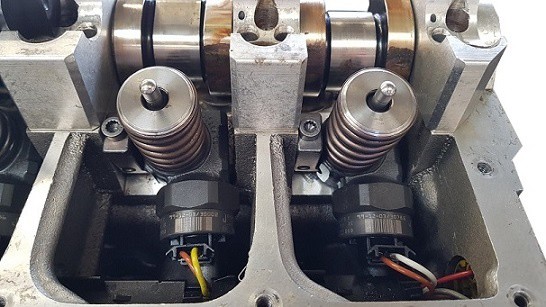
3. Remove and install the unit injector.
Use the puller to pull the unit injector out of the cylinder head. Hook the protruding part of the puller into the part where the clamping block hooks into the unit injector.
Fit new O-rings on the injector before it is reinstalled. Then carefully press the injector into the cylinder head and install the clamping block. Do not tighten the bolt yet, because the injector can no longer be rotated for adjustment if you do.
In the image, the injector of cylinder 3 (the left one) has been replaced. It is visibly skewed. The adjustment is done in step 4.
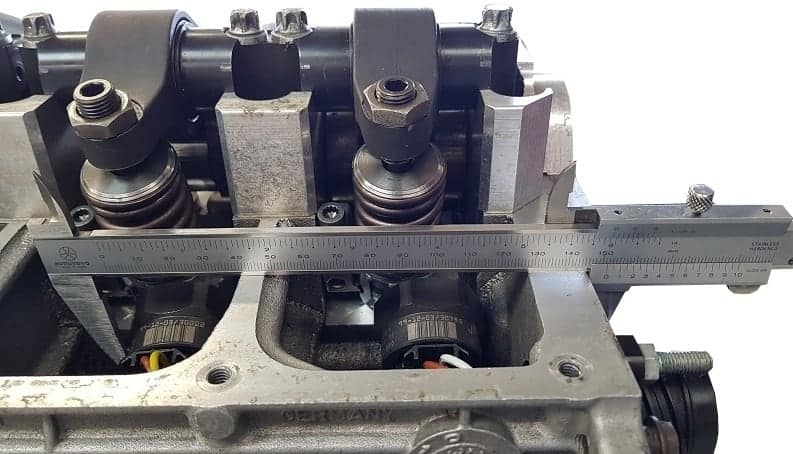
4. Adjust the position of the unit injector.
Using the vernier caliper, the distance between the bulge of the injector and the outer side of the cylinder head must be measured. This can be seen in the image.
If the measured value does not correspond to the value specified by the manufacturer, the injector must be rotated. The bulge of the injector will then have a different distance to the outside of the cylinder head.
The specified value of this distance is: 151.3 mm ± 0.9 mm. That means that in the ideal situation the dimension should be 151.3 mm, but a deviation of 0.9 mm is allowed. The measurement is shown in the image below and the next image shows an enlargement of the reading on the scale of the caliper.
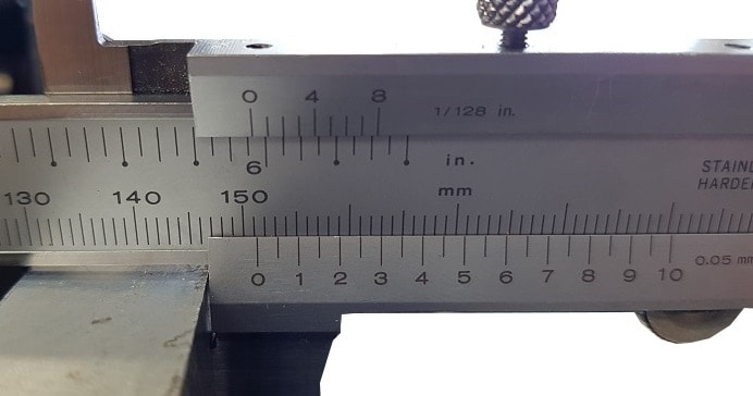
The image shows an enlargement of the scale of the caliper for the measurement in step 4. The dimension indicated here is 151.3 mm. This is the value specified by the manufacturer. The bolt of the clamping block can be tightened.
The right measuring jaw of the caliper must be kept on the cylinder head when measuring the other unit injectors. The adjustment values of the other injectors will therefore all be different. To be able to take the measurement at the injector of cylinder 1 (timing belt side), the caliper must have a measuring range of 400 mm.
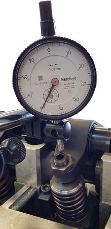
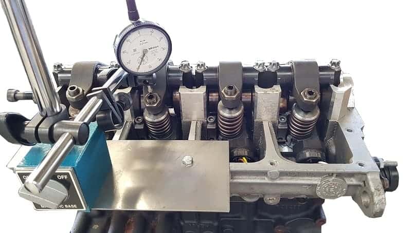
5. Install the dial gauge.
Install the dial gauge on the injector that has been replaced. Let the dial gauge rest on the side of the rocker arm that moves down when operating the unit injector.
Because the needle of the dial gauge must always touch the rocker arm, the dial gauge must be pressed against the rocker arm with a preload. When moving up and down, the needle will always touch the rocker arm. Ensure that the preload is at least 3 mm.
6. Turn the crankshaft until the rocker arm has reached its lowest point.
The purpose of this measurement is to measure the lowest point of the rocker arm. The measurements below are performed on the unit injector of cylinder 2.
When turning the crankshaft, the rocker arm will drop, so the value on the dial gauge will decrease. The needle will move counter-clockwise.
At the moment the lowest point is reached, the needle will stop moving. When the crankshaft is turned further, the needle will start to rise again. At the point in between, where the needle remains stationary, the rocker arm has reached its lowest point and the adjustment procedure must be followed.
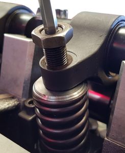
7. Adjusting the unit injector (1).
Loosen the locknut and then turn the adjusting screw all the way up until the rocker arm touches the upper ring of the unit injector.
8. Adjusting the unit injector (2).
Turn the adjusting screw as far as possible into the rocker arm. The spring of the unit injector is compressed in the process. Turning can be heavy. Stop turning when much resistance is felt, because at that moment the plunger in the unit injector touches the bottom of the high-pressure chamber.
9. Turn the adjusting screw back 180°.
Now that the adjusting screw is fully tightened to its stop, it must be turned back half a turn. In this way it is prevented that every time the camshaft operates the unit injector, the plunger in the unit injector touches the bottom of the high-pressure chamber.
If several unit injectors have been replaced, this measurement must be repeated for each injector. Take careful note that the adjustment instructions may differ for each engine code or year of manufacture!
No rights can be derived from the above instructions and images.
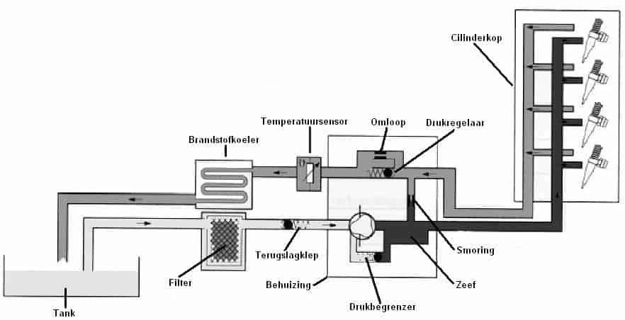
Fuel feed pump:
The fuel feed pump is a vane pump with spring-loaded vanes. It is located between the fuel filter and the injectors. The pump is driven by the camshaft. Inside the pump there is a pressure limiting valve that limits the pressure in the feed line to 7.5 bar. A valve is fitted in the pump that keeps the pressure in the return line from the unit injectors constantly at about 1 bar.
Modified timing drive:
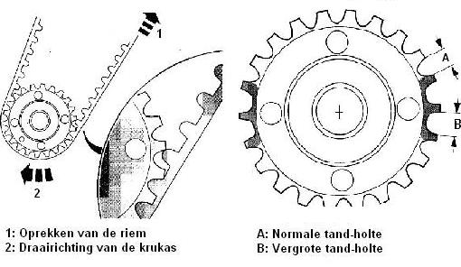
Because the pressure in the unit injectors can rise to about 2000 bar, the engine timing drive is subjected to additional load. To prevent the belt from breaking, a number of measures have been taken:
- The crankshaft sprocket of the timing drive has slightly larger tooth gaps in two places. At the moment the unit injector builds up high pressure, the timing belt will be stretched. As a result, the pitch of the teeth will increase slightly. This is compensated by making the tooth gaps slightly larger in two places.
- The timing belt has been made wider, which makes it stronger.
Fuel cooler:
As the name suggests, the function of the fuel cooler is to cool the fuel. The fuel cooler is located near the radiator or under the car. There is a continuous flow of fuel through the entire system. The fuel that returns to the tank has been significantly heated by the cylinder head of the engine. The fuel cooler cools the return fuel that goes back to the tank.
Related pages: