Introduction:
Up until the early 1990s, car manufacturers produced new petrol engines in which the fuel supply was controlled by a venturi carburetor. The carburetor is located on the engine’s intake manifold. In the carburetor, the supply and mixing of petrol and air takes place.
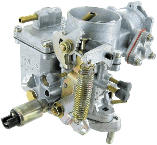
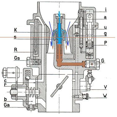
The image shows a carburetor of the brand Solex which was used, among others, on the VW Beetle. Other well-known carburetor brands are: Zenith, Stromberg, Weber, Rochester, Holley, Binks, Carter and S.U.
Engines equipped with a carburetor could no longer meet the requirements from the introduction of the latest emission standards (Euro 1). Since then, the carburetor has been replaced by the computer-controlled engine management system, which is still being further developed to this day.
Because new cars have not been fitted with a carburetor for almost three decades, this subject is often no longer included in the teaching material of current automotive technology courses.
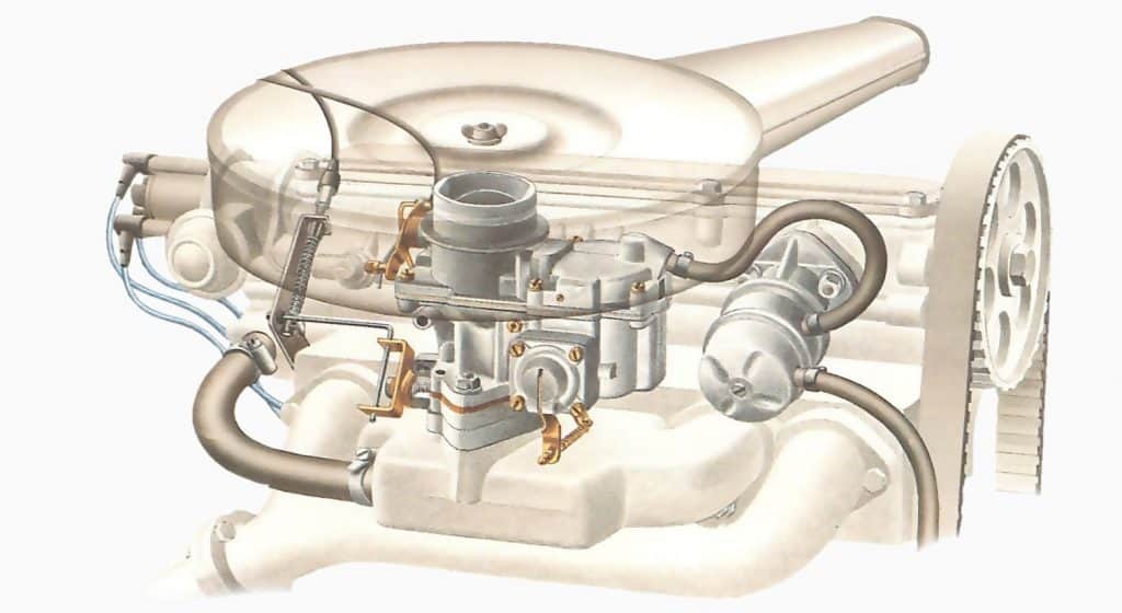
The carburetor is positioned between the intake manifold and the air filter. The image below shows the position of the carburetor on the engine.
Different carburetor types:
The way in which the carburetor is mounted on the engine affects the flow direction. The image below shows the downdraft (left), updraft (middle) and sidedraft carburetor (right).
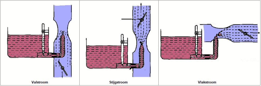
- Downdraft: the air enters at the top and flows downward. The fuel flows with the direction of the air and, with the help of gravity, to the cylinders. This type is the most commonly used.
- Updraft: the airflow is in an upward direction. The weight of the fuel results in a less easy flow than with the downdraft carburetor. This type was no longer used in the final years of the carburetor era.
- Sidedraft: located in a horizontal direction.
Main section:
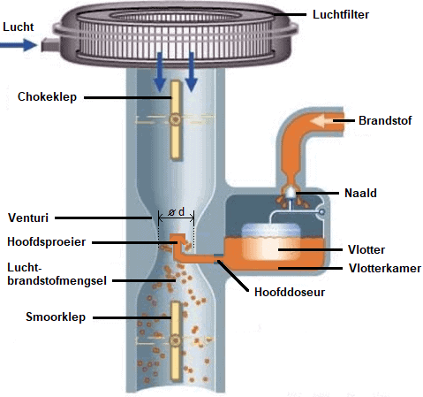
A mechanical fuel pump supplies the carburetor’s float chamber with petrol. As the fuel level rises and the float element floats, the supply line is closed by the needle. The needle opens the supply as soon as the fuel level drops. From the float chamber, the petrol enters the main jet via the main metering orifice. The fuel level in the main jet is kept below the jet opening by the level in the float chamber. If the needle does not seal properly (due to a defect or contamination), the fuel level in the float chamber becomes too high and too much fuel flows through the main jet to the engine.
The throttle plate / throttle valve is connected to the accelerator pedal. The opening angle of the throttle plate influences the vacuum and airspeed in the venturi (restriction in the intake tube). The amount of petrol drawn from the main jet depends on this vacuum. As the airspeed increases, a higher vacuum is created, causing more petrol to be added to the air. The optimal fuel / air ratio depends on the size of the main metering orifice in relation to the diameter of the venturi. The size of the main metering orifice is suitable for a very limited speed range. The mixture quantity determines the engine torque.
The relationship between the increasing airspeed and the corresponding vacuum and the outflow of petrol can result in mixture enrichment that continues to increase. The jet with air-bleed control compensates for this. In a mechanical way, the air-bleed system tries to keep the air-fuel ratio stoichiometric. The holes in the air-bleed tube(s) are intended to prevent enrichment and to keep the mixture stoichiometric. The air-bleed holes have different diameters.
- Low speed: vacuum is relatively low, petrol flows out of the main section from the main metering orifice.
- Higher speed: vacuum increases, more petrol is drawn in than the main metering orifice can supply and therefore limits the fuel flow. The level in the emulsifying tube(s) drops, exposing the first air holes in the tube. The air from the air metering orifice is mixed with the petrol.
Due to the air supplied, the vacuum decreases and the fuel flow is slowed down. The higher the engine speed, the more air holes are exposed and the more air-bleed air is mixed with the petrol. At very high speeds it may happen that the tube is completely empty and air is drawn in from the idling section.
Cold start:
To obtain a sufficiently rich mixture during starting, we see two designs:
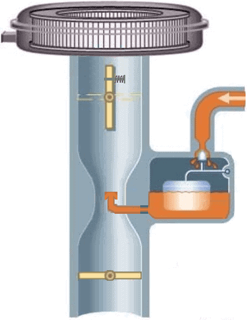
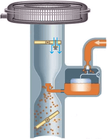
Design with choke plate:
The explanation applies to the two images below. The choke plate is located at the top of the carburetor. There is a hole in the choke plate which, at rest, is closed by a spring-loaded valve. When starting a (cold) engine, the choke plate can be manually pulled shut. The vacuum “sucks” the valve open so that air can be drawn in. Due to the small air opening, a large vacuum occurs in the main section during starting so that petrol is also drawn in. The throttle plate must be partly opened, otherwise there will be no vacuum at the main jet. A linkage between the two plates makes it possible to operate both at the same time, without having to press the accelerator pedal. After the engine has started, the choke can be opened again. At a warm outside temperature this can be done sooner than at temperatures around freezing.
Design with starting carburetor:
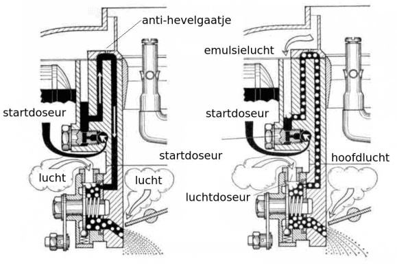
The starting carburetor does not use a choke plate but has a separate fuel supply section. The image below shows a carburetor of this type.
For a cold start, the throttle valve must be closed. At the moment the driver operates the choke knob, a slide in the carburetor rotates and openings create a connection with the starting section of the carburetor. The petrol is drawn in from the starting metering orifice and mixes with the incoming air in the air metering orifice. The vacuum under the throttle plate draws the air-fuel mixture in. In this situation, the throttle plate is still closed. After the engine has started, the higher vacuum draws the fuel tube from the starting metering orifice empty. The emulsifying air ensures additional air to prevent an overly rich mixture.
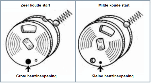
The control slide can be designed with two flow openings of different diameters. The driver can then choose between a very cold start, a mild cold start and warming up the engine.
Idling and transition section:
When idling, the throttle plate is closed and there is a high vacuum under this throttle plate. Due to the small airflow, there is too little vacuum in the venturi to draw fuel from the jet. Under the throttle plate, however, there is a high vacuum. In this situation, an extra fuel channel under the throttle plate supplies the engine with the correct amount of petrol. The image is of a Solex carburetor.
The adjusting screw for setting the mixture quantity affects the CO value. The idling speed must be adjusted with the screw on the throttle valve.
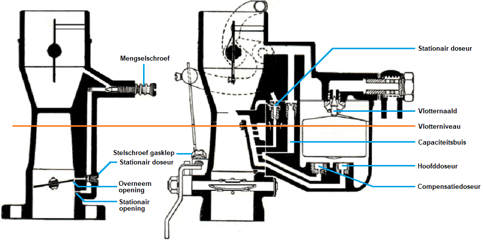
The image below shows the idling section (left) and the main section (right) of a Zenith carburetor. The Zenith has many similarities with the previously described Solex carburetor.
The idle opening is located under the throttle plate and the transition opening just above the throttle plate. When the driver begins to accelerate, the transition section supplies extra fuel. After that, the main section takes over. The main section also provides the fuel supply during idling. The fuel passes the idle metering orifice and the adjustable mixture screw. At the throttle plate, a second idle metering orifice is mounted. The speed must be adjusted with the throttle stop screw. The main metering orifice and compensation metering orifice are both mounted at the bottom of the float chamber and form the main section. The capacity well serves as a reservoir and is filled with fuel.
Acceleration:
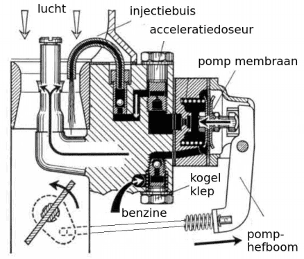
A Solex carburetor is equipped with a mechanically or pneumatically operated accelerator pump. When the accelerator pedal is pressed quickly, a richer mixture is required for a good mixture ratio and more power. The spring is tensioned and moves the pump diaphragm to the left. The petrol is injected into the venturi via the diaphragm, the accelerator metering orifice and the injection tube.
The ball valves ensure the suction and discharge of the fuel and depend on the spring force. The tension can be adjusted manually.
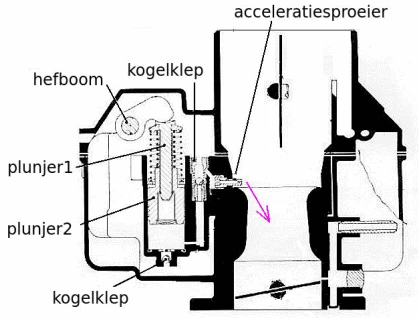
The following image shows the mechanically operated acceleration section of a Zenith carburetor. The inner plunger is pushed down when the accelerator pedal is depressed. Fuel injection takes place via the accelerator jet. The spring of the outer plunger is tensioned, so that the injection duration depends on the gradually relaxing spring tension. It is not the position of the lever, but the spring tension that determines the injection time. Two ball valves ensure – just as with the Solex carburetor – the suction and discharge of the petrol.
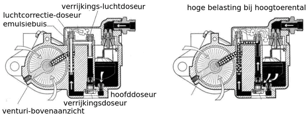
Full load:
The mixture must also be enriched at full load and higher engine speeds. The carburetor can be equipped with a separate enrichment section that is part of the main section. During part load, only the main section supplies fuel. Higher load and higher engine speeds create more vacuum in the venturi. Due to this vacuum, extra fuel is drawn in via the enrichment metering orifice (see image).