Introduction:
Common-rail is an injection system that has been used on diesel engines since 1997. The injectors are controlled by the engine control unit. Both the opening and closing of the injector (the injection duration) and the number of injections per combustion cycle are determined by the engine control unit. The engine control unit calculates the injection duration on the basis of a number of factors, such as engine speed, load, ambient air and engine temperature, etc.
The high-pressure pump supplies fuel pressure to the fuel rail. There is always a constant pressure in the fuel rail. All injectors are connected directly to the fuel rail. The fuel pressure is therefore also directly present on the feed line of each injector. Only when the injector receives an opening signal from the engine control unit will it open. The pressure from the fuel rail will then enter the cylinder via the injector. Injection stops as soon as the engine control unit ends the signal.
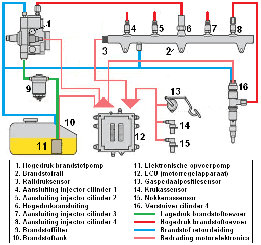
The green line represents the low-pressure fuel supply line.
The electric feed pump (11) pumps the fuel at a pressure of max. 5 bar via the filter element (9) to the high-pressure pump (1). From the high-pressure pump, a high-pressure line (red) runs to the fuel rail. In the fuel rail there is a fuel pressure that depends on the speed of the high-pressure pump. The rail pressure sensor registers this value and constantly sends the current fuel pressure to the engine control unit.
The high-pressure lines of all injectors are connected to the fuel rail, as can be seen with fuel rail number 8 and injector number 16. The return line (blue) ensures that all surplus fuel from the injector, the fuel rail and the high-pressure pump is returned to the tank. There is a constant circulation of fuel to cool the components, which are often located in the engine compartment.
Differences between the conventional injection system and common-rail:
In (conventional) diesel engines without common-rail injection (so with a high-pressure in-line pump, rotary distribution pump or an electronically controlled distributor pump) the injectors are opened by the pressure of the fuel itself.
The fuel pump rotates at camshaft speed and builds up pressure at the right moment. The pressure build-up and injection therefore depend on the timing of the fuel pump in relation to the camshaft. That is why when replacing the timing belt, the fuel pump must always be locked as well.
In common-rail engines, the fuel is injected at the moment the engine control unit sends a signal. In the first generation of common-rail engines, the position of the pump therefore did not matter. It could be rotated into any position when fitting the timing belt. The pump supplies a constant fuel pressure to the injector rail.
Nowadays, all engines are adjusted much more precisely. The pump often has to be locked now as well. This is to counter vibrations related to the pressure build-up of the pump. The pumps are now designed so that the peaks of the pressure build-up occur at the same moment as the compression stroke of the engine. This makes the engine run more smoothly and the timing belt is subjected to less load.
Low-pressure section:
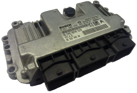
The low-pressure section comprises the fuel tank, the electric feed pump, the fuel filter, the low-pressure fuel line and the return line. These components are described below.
- Fuel tank: this is where the fuel is stored. The tank capacity can vary between 30 and 70 litres for lighter and heavier luxury passenger cars. Click here for more information about the fuel tank.
- Electric feed pump: is mounted in the tank. This pump ensures that the fuel is pumped from the tank at low pressure to the high-pressure pump (in the engine compartment). In common-rail diesel engines an electric feed pump is not always present. Sometimes a gear pump is built into the high-pressure pump. From the high-pressure pump, the fuel is therefore both drawn from the tank and pressurised towards the fuel rail. Click here for more information about the feed pump.
- Fuel filter: fuel may contain contaminated particles. These particles remain trapped in the filter medium so that they cannot enter the injection system. The fuel filter also serves as a water separator. Diesel fuel also contains moisture. This moisture is very harmful to the pump and the injectors / lines. It can cause corrosion on the inside of the components. To prevent this, the water is also separated from the fuel and remains behind in the filter. This filter must be periodically drained and/or replaced.
- Low-pressure fuel line: this fuel line runs from the electric feed pump to the high-pressure pump. The pressure in this line is approximately 5 bar.
- Fuel return line: the fuel that is pumped in excess flows back to the tank via the return line. The return fuel is also used for cooling, as it dissipates heat. There must therefore always be return fuel present. At the moment of deceleration (engine braking) no fuel is injected into the combustion chamber. The amount of return fuel is greatest at that moment.
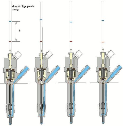
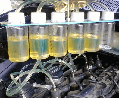
The return fuel can also be used to recognise whether an injector remains unintentionally open. This may be caused by contamination or a defect in the injector, or an error in the control by the engine control unit. By disconnecting the return lines of all injectors and collecting them at the same time, the differences can be compared. If one injector has noticeably little return fuel, it is very likely that the injector is remaining open for too long. Too much fuel is being injected. This is shown in the image below. Here one injector has no return fuel.
High-pressure section:
The high-pressure section comprises the high-pressure pump, the fuel rail, the high-pressure fuel lines and the injectors.
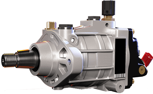
- High-pressure pump
The high-pressure pump is designed as a plunger pump and ensures that the fuel pressure in the fuel rail (depending on the system) remains at a constant level. This is 1300 bar in the first generation common-rail engines (from 1997) up to 2000 bar in current systems. The higher the injection pressure, the smaller the fuel droplets and the better the combustion and thus the exhaust gas emissions. The amount of fuel the pump delivers to the fuel rail is reduced as the engine requires less. The pressure then remains roughly the same. By actuating an electromagnetic overflow valve, a control plunger is moved further and further as a result of spring tension. The rail pressure then decreases. On the High-pressure fuel pump page, the operation of several types of high-pressure pumps, including that of the common-rail diesel, is explained in detail.
- Fuel rail
From the high-pressure pump, the fuel is pumped to the fuel rail. There is a constant fuel pressure in the fuel rail. From the fuel rail, fuel lines run to the injectors. The rail pressure sensor is also connected to the fuel rail (if the rail pressure becomes too high, the engine management will ensure that the pressure relief valve opens) and a return line is present.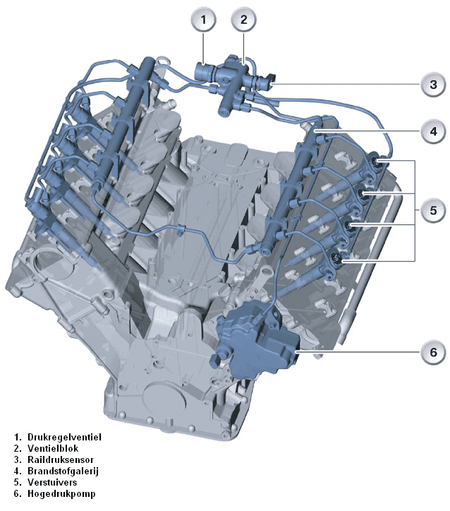
- High-pressure fuel lines
Because high-pressure fuel lines are subjected to high pressures, they must be of robust design. They are made of metal and are connected to both the pump and the injectors with union nuts. These high-pressure fuel lines carry the fuel from the high-pressure pump to the fuel rail and from the fuel rail to the injectors. The lines between the fuel rail and the injectors are all the same length and thickness. This prevents differences in injection between cylinders. If the distance between the fuel rail and cylinder 1 is greater than between the rail and cylinder 4, a bend is made in the line to cylinder 4. This bend ensures that the distance the fuel for cylinder 4 has to travel is still as long as for cylinder 1. - Injector
Electromagnetic or piezo injectors are used. With these injectors, the injection quantity, injection profile and injection timing can be controlled. There is a constant fuel pressure at the inlet of the injector. This is the same pressure as in the fuel rail. This pressure is also present in the control chamber as long as the solenoid valve is closed. The solenoid valve is controlled by the ECU.
As soon as the solenoid valve is actuated by the engine management, the injector needle is lifted and the injector sprays a certain amount of fuel in. Because the rail pressure and the injector openings are always constant, the engine management knows exactly how much fuel is injected in a given time. Because after production there is always a minimal deviation, this deviation must be communicated to the engine control unit. After production, the injector is tested. Based on the results of, among other things, the opening pressure and injector quantity, a code is determined. This code is engraved on the injector and can be read by the technician (see the image below, the code here is 574-221). This way of teaching-in is the same for both a petrol and a diesel engine.
Measuring voltage and current pattern on the electromagnetic injector:
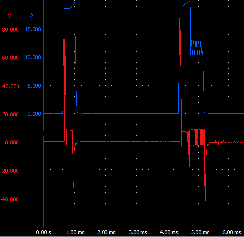
The voltage and current pattern across the electromagnetic injector can be measured using an oscilloscope. This can be used to determine whether the injector is being controlled correctly by the ECU.
In the scope image below, the red line is the voltage pattern and the blue line is the current pattern. In the scope image above, two injections can be seen. The left one is the pre-injection and the right one the main injection. In other engines, there can even be three injections in succession.
The injector opens at a high voltage and current. The voltage is approximately 80 volts. This high voltage can be achieved thanks to a capacitor in the ECU. This high voltage in combination with a low resistance of the coil ensures a fast response of the injector. The injector therefore has a short turn-on and turn-off delay. Because the current through the coil generates a lot of heat, it must be limited. Without current limitation, the actual current would rise to as much as 300 amperes. However, that value will never be reached because the injector coil would have burned out long before.
The current limitation can be seen from the voltage that is repeatedly switched on and off between 4.6 and 5.1 ms. During this current limitation, the voltage (12 volts) and the current (12 amperes) are still high enough to keep the injector needle open.
At 5.1 ms the actuation is stopped and the injector needle will close.
Engine electronics:
The engine management system (ECU) calculates, on the basis of data from sensors (accelerator pedal position sensor, engine temperature, vehicle speed, crankshaft speed, air quantity (air mass meter), intake air temperature, exhaust gas quality (NOx)), the amount of fuel that must be injected and the moment at which it must be injected. Controlling the injectors is a demanding task. To be able to supply a current of more than 20 amperes in a short time (max. 300 milliseconds), a voltage of up to 80 volts is required.
This is achieved with the charge of capacitors and output amplifier stages.