Introduction:
In modern vehicles, the alternator’s charging state is adjusted to conditions. The alternator is controlled from the engine ECU and receives signals to charge more or less. The alternator generates energy as a magnetic field is created between the rotor and stator. The larger the magnetic field, the more force is required to turn the rotor. Generating a large amount of charging current therefore costs energy and fuel.
- The idle speed can be increased when the battery is almost empty at the moment that insufficient charging is possible;
- During maximum acceleration the alternator is temporarily not activated, so all generated torque can be used for propulsion;
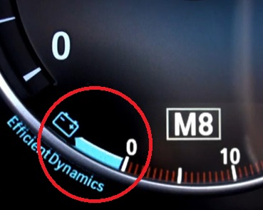
- During deceleration (engine braking) the ECU drives the alternator at maximum, so that the vehicle’s kinetic energy is used to generate energy in the alternator. In the image the indication of the maximum battery charge (12-volt system) can be seen.
The signal from the intelligent battery sensor is used to determine the state of charge of the battery. This is one of the most important data points to determine to what extent the alternator needs to be controlled.
Intelligent battery sensor:
Modern vehicles are almost all equipped with a battery sensor, often known as an IBS (Intelligent Battery Sensor), current sensor or battery monitor. In this article we will refer to the term “battery sensor”. The battery sensor works in close cooperation with the Battery Monitor System (BMS) in the vehicle. This applies in particular to vehicles with a start-stop system. In these vehicles the battery is repeatedly heavily loaded, as the starter motor is activated several times per trip to start the engine. Therefore, such vehicles often use an AGM battery instead of a traditional lead-cell battery. An AGM battery is better able to withstand repeated discharging and charging.
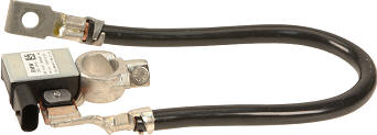
The battery sensor is integrated into the ground cable, which is mounted between the negative terminal of the battery and a ground point on the bodywork or chassis. On the battery sensor you will find a connector with two or more wires. One wire goes directly to the positive terminal of the battery, and a second wire is used for communication.
Inside the housing of the battery sensor is a circuit board with a microprocessor and a controller that measures voltage, current, temperature and time. The data from this Electronic Control Unit (ECU) is often transmitted via a LIN bus to the alternator and the body control module (BCM) or the engine control unit. Between the battery sensor and the BCM or engine control unit there is usually a gateway to translate the LIN bus message into a CAN bus message. This is discussed in more detail in the paragraph “diagnostics on the intelligent battery sensor”.
The battery sensor monitors the condition of the battery and measures the following parameters:
- The battery voltage.
- The current with which the battery is charged and discharged.
- The temperature of the battery.
The battery sensor sends this data to the engine control unit or BCM. Using this data, the ECU (Electronic Control Unit) calculates the following:
State Of Charge (SOC) of the battery. By measuring the outgoing current to the consumers and the incoming current to the battery, it can be determined how much energy is still available in the battery.
Condition (State Of Health, SOH) of the battery. The battery voltage and discharge current are compared to assess the quality of the battery. During starting, up to 60 A of current can be drawn from the battery for a small petrol engine, or as much as 120 A for a heavier diesel engine. The extent to which the battery voltage drops indicates how large the internal resistance in the battery is. If the voltage drops from 11.5 to 10 volts at a current of 60 A, this is acceptable. If, with the same starting current, the voltage drops from 11.5 to 8 volts, this indicates excessive internal resistance in the battery and replacement is necessary.
Quiescent current when the vehicle is parked. This enables detection of an abnormal quiescent current, for example due to an unauthorised consumer. The driver receives a warning during the next journey if an increased quiescent current is detected.
Components and measuring principles of the battery sensor:
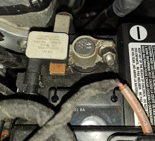
The housing of the battery sensor and the ground terminal are often integrated into one unit. The ground cable may also form one piece with the battery sensor or be attached with a screw connection. Inside the battery sensor is a shunt resistor with a very low resistance value. By measuring the voltage difference across this shunt, the current can be calculated. In combination with the battery voltage, the power with which the battery is charged or discharged can be calculated.
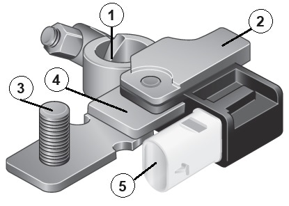
1. Terminal clamp for ground terminal;
2. Battery sensor;
3. Vehicle ground connection;
4. Shunt;
5. Connector for B+ and LIN bus.
The shunt resistor is placed in series between the vehicle’s ground connection and the negative terminal of the battery. All current to and from the battery passes through this shunt. Because of the low resistance value, little voltage is consumed in the shunt.
The level of this voltage is converted in the microprocessor, together with the known resistance value of the shunt, into a current:
- A large voltage drop across the shunt indicates a large current.
- A low voltage drop indicates a low current.
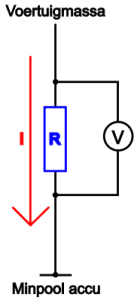
In the attached image we see a diagram in which the resistor R represents the shunt and the current I represents the discharge current when the battery is being discharged. The voltmeter, which is placed in parallel across the shunt resistor, illustrates how the measuring electronics in the battery sensor measure the voltage difference across this shunt.
The image below provides an overview of the locations where temperature, voltage and current measurements are taken.
The shunt resistor is indicated by number 5. The voltage difference (V) across the shunt is read as current (A). Via the LIN bus this data is sent to the DME/DDE, which are the designations for BMW’s petrol engine (DME) and diesel engine (DDE).
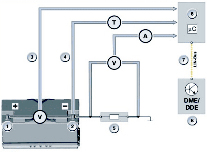
1. Battery positive terminal;
2. Battery negative terminal;
3. Measurement of battery voltage;
4. Measurement of battery temperature;
5. Measurement of current by means of a shunt resistor;
6. Microprocessor in the intelligent battery sensor;
7. LIN bus communication wire
8. Engine control unit
Charging and replacing the battery:
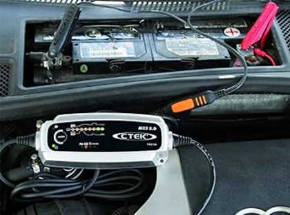
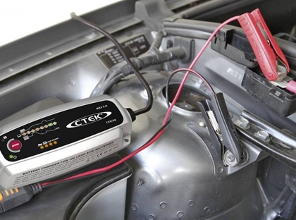
The battery management system uses the battery sensor to measure the current flowing to and from the battery and to store this information in memory. When the battery needs to be charged or a jump-start is used, it is important that the battery charger is not connected directly to the battery terminals, but to the charging points. The battery sensor is located between these charging points and the battery terminals and can only measure the energy flow when the battery charger is connected to the charging points. If the battery charger is connected directly to the battery terminals, the BMS memory will indicate that the battery is (almost) empty, while in reality it is fully charged. The alternator will then overcharge the battery, after which the system will go into fault mode. The images below show a battery charger connected directly to the battery and to the charging points under the bonnet.
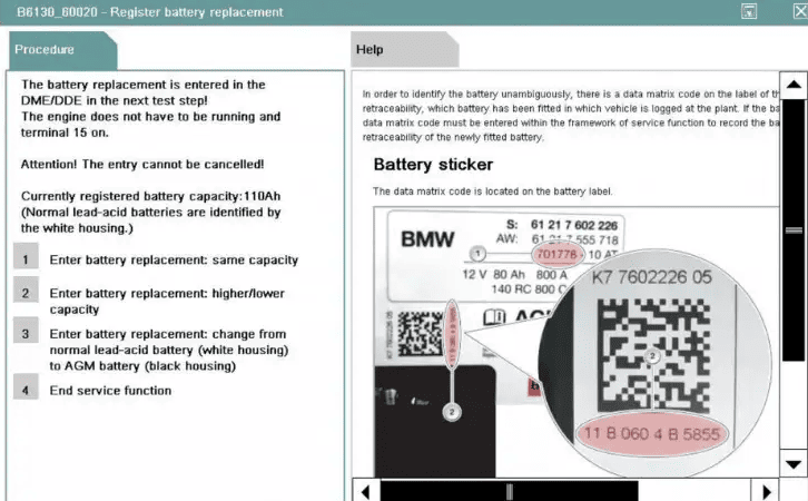
After replacing the battery in a vehicle equipped with a battery sensor, the battery must be registered. In the workshop this is also called “learning” or “coding” the battery. The battery management system takes into account:
- the aging of the battery. The charging current for an older battery with increased internal resistance can be increased;
- the capacity and the cold cranking current of the battery.
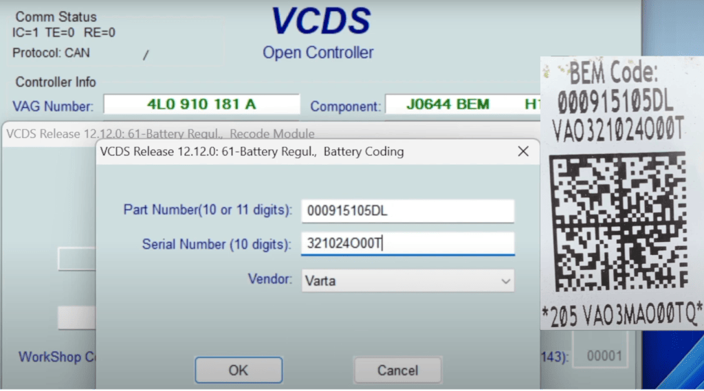
During registration, the stored values of the battery that has deteriorated over time are erased. So even when an identical battery of the same brand and with the same capacity and cold cranking current is installed, the replacement must be registered. Naturally, the details of a battery with different characteristics must be entered. This can be done by manually entering the capacity [Ah] and the cold cranking current [A], or by filling in the part numbers or serial numbers. With modern diagnostic equipment, the QR code shown on the battery label can be scanned.
The screenshots below show the registration of a battery in a BMW program (left) and VCDS (right).
Diagnostics on the intelligent battery sensor:
The intelligent battery sensor communicates with the alternator and the BCM or engine control unit. This paragraph explains how to read the wiring diagram and in what way a diagnosis can be made.
In the following wiring diagram we see the battery sensor (A85) which is supplied with a 12-volt supply voltage via a fuse on pin 2. Pin 1 is for communication: from here a message is sent via LIN bus to the gateway (A25di) and the alternator (O01). Pins 1 and 2 are located in the two-pin connector that was visible in earlier images.
The two lower black wires on the battery sensor do not have a pin number: this is a direct connection to the negative terminal of the battery.
The intelligent battery sensor sends a LIN bus message to the gateway and the alternator. The gateway is the node between networks with different protocols (voltages and speeds). In the gateway, the LIN bus message is sent via CAN bus to the BCM and/or engine control unit. Conversely, one of these two control units controls the alternator via the gateway and LIN bus.
A fault in LIN bus communication can prevent the data from the battery sensor from being used, or can cause the alternator not to be controlled correctly. In the latter case, the alternator switches to an emergency program in which the conventional D+ control is used to still create sufficient charging voltage and charging current.
The voltage pattern of the LIN bus signal can be measured with an oscilloscope to determine whether there is a fault in the LIN signal.
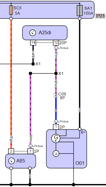
Legend:
P01: fuse box, engine compartment
A25di: diagnostic interface (gateway)
A85: ECU battery sensor
O01: alternator
When a fault is present and the LIN bus communication is in order, we know that the sensor’s power supply and ground are good. The fault is then caused by one of the components in this wiring diagram. The following steps can be carried out:
- check for software updates of the control units;
- test the 12-volt battery (preferably under load);
- check whether the correct battery data have been registered. The battery may have been replaced in the past, but registration was never performed;
- reset the data of the battery sensor;
- check whether the part number of the alternator is correct: an incorrect alternator that does not match the sensor will eventually cause problems;
- if the above has been checked and found to be in order, one may conclude that the battery sensor is defective. This sometimes occurs after frequent (incorrect) jump starting using jumper cables or a booster pack.
Related pages: