Introduction:
The purpose of a gearbox is to adapt the engine speed, and thus the available engine torque and power, to different driving conditions. These may include accelerating or decelerating, transporting a heavy load, driving up and down hills, and changes in air and rolling resistance that can occur while driving. By shifting to a more suitable gear in these different conditions, this will in most cases result in more favorable fuel consumption and more torque and power.
In a low gear (for example, second gear) more engine torque is available than in a higher gear (e.g. fourth gear). This is because in second gear the engine’s crankshaft makes more revolutions and reaches higher revs much quicker during acceleration than in a higher gear. It is therefore wiser, when driving with a heavy load such as a caravan, not to drive in too high a gear, especially not in the mountains.
Between the engine and the gearbox is the clutch, which consists of a clutch plate, a pressure plate and a release bearing. By pressing the clutch pedal, the pressure plate is operated via a cable. With a hydraulic clutch, fluid is transferred from one cylinder to the other by means of two clutch cylinders.
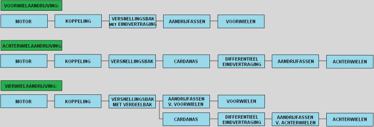
Below is a block diagram showing how the drive from the engine to the wheels is achieved with front‑wheel, rear‑wheel and four‑wheel drive. For more information, see the page drive types.
Single and double reduction:
Manual gearboxes are divided into two groups: single and double reduction. Reduction is another word for transmission. It basically means “single and double” transmission. Below is an illustration of what is meant by this.
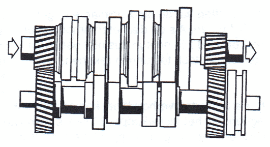
Single reduction
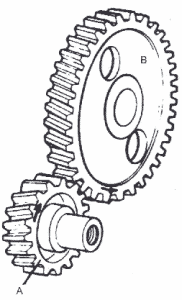
The gears on the input and output shafts are directly connected to each other.
A: Input shaft (primary shaft, from the engine)
B: Output shaft (main shaft)
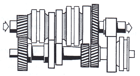
Double reduction
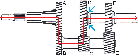
First gear is engaged; in first gear the drive forces run from A to B and from C to D.
Via the input shaft, a force is applied to gear A. This gear is directly connected to gears B, D and E. Because first gear is engaged, the synchronizer unit has connected the output shaft to gear D (see blue arrows). From gear B the drive forces leave the gearbox via the output shaft. The output shaft drives the differential, which may be located inside the gearbox (in front‑wheel‑drive cars) or the differential may be mounted elsewhere, as in a rear‑wheel‑drive car. This will be explained in more detail later on this page.
A: Gear on input shaft (primary shaft, from the engine)
B, C & E: Gears on secondary shaft
D & F: Gears on output shaft (main shaft)
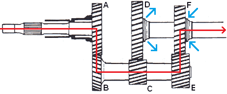
Second gear is engaged. The synchronizer unit is disconnected from gear D and connected to gear F (see the blue arrows). At that moment gear D still rotates, but it is no longer connected to the output shaft. Gear F is connected, so the drive forces now go from A to B and from E to F.
Because gears C and E have different sizes, the transmission ratios have changed. As a result, after engaging the clutch, the engine speed has dropped at the same vehicle speed.
Gearbox in longitudinal or transverse position:
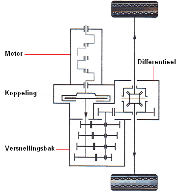
The illustration shows a schematic of a rear‑wheel‑drive car. The engine block is mounted longitudinally (in the lengthwise direction) and the gearbox is a double‑reduction type. The final drive (the differential) is located at the rear axle and drives the rear wheels. This is the type of drive that BMW, among others, frequently uses.

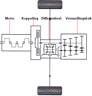
This illustration shows a schematic of a front‑wheel‑drive car. The engine block is mounted transversely (sideways) and the gearbox is a single‑reduction type.
The drive forces enter via the input shaft (the primary shaft) and are transmitted to the output shaft through the engaged gears. The differential is integrated in the gearbox housing. This type of drive is used in, among others, the Volkswagen Golf and Ford Focus (and of course in many other brands!).
The illustration shows a schematic of a front‑wheel‑drive car. Here both the engine block and the gearbox are mounted longitudinally. The engine block is located in front of the front axle and the gearbox behind the front axle. The differential is mounted at the height of the drive shafts. This system was used, among others, on older types of VW Passat, Skoda Superb and Audi A4. The newer models now have a transversely mounted engine block (so the situation shown below).
Gears and gear ratios:
With different gear sizes, different transmission ratios can be achieved. We call these transmission ratios gear ratios. When a large gear is driven by a small gear, the small gear can, for example, make 3 revolutions while the large gear only makes 1. The transmission ratio is then 1:3. The reduction and torque multiplication are then 3 times as great. If the small gear has 20 teeth, the large gear will have 60 teeth.
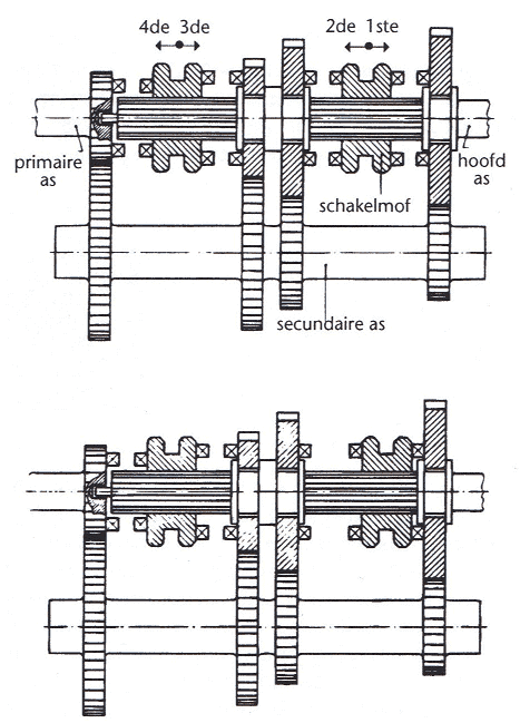
Below are the various gears that can be selected. You can see that in each gear, the right‑hand gear on the top shaft (the primary shaft) for gears 2 and 3 becomes progressively smaller, while the gear on the right‑hand side of the secondary shaft becomes progressively larger. This increasingly enlarges the transmission ratio, which is the ultimate goal when shifting to another gear.
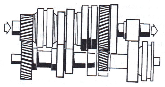
First gear:
The drive force enters on the left at the arrow on the primary shaft. The drive force is transmitted directly to the gear on the secondary shaft. The secondary shaft is the lower shaft. The smallest gear on the secondary shaft is connected to the second‑to‑last gear on the output shaft. Due to the size of the gears, the output shaft rotates much more slowly than the input shaft. This creates the greatest reduction. First gear has the greatest reduction so that you can accelerate from standstill with a large torque increase.
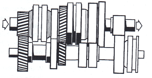
Second gear:
The gears on the left remain engaged. The drive force goes via the third gear on the secondary shaft to the third gear on the output shaft. The output shaft still rotates more slowly than the input shaft. So there is still a reduction. However, the reduction is now smaller than in first gear, so at the same engine speed a higher vehicle speed can be achieved than in first gear.
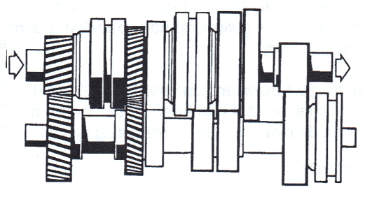
Third gear:
The drive force goes via the second gear on the secondary shaft and the second gear on the output shaft. The output shaft still rotates more slowly than the input shaft. The reduction is now again smaller than in second gear, so once more a higher vehicle speed can be achieved at the same engine speed than in second gear.
Fourth gear:
This is called direct drive. The drive force goes from the primary shaft directly to the output shaft. The engine torque is therefore transmitted 1:1 to the wheels. The gearbox in effect is not providing any reduction or increase.
In a 5‑speed gearbox, fourth gear is always direct drive. However, in a 6‑speed gearbox, fifth gear is direct drive.
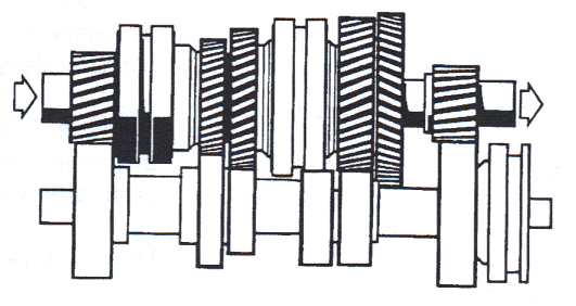
Fifth gear:
In fifth gear the two rearmost gears are connected to each other. Here the largest gear on the secondary shaft is coupled to the smallest gear on the output shaft. This is called ‘overdrive’. The output shaft now rotates faster than the primary shaft.
Gears 1, 2 and 3 are reduction gears; the input shaft rotates faster than the output shaft. In fourth gear the input shaft rotates at the same speed as the output shaft (direct drive). In this 5th gear there is therefore a true overdrive, because in this gear alone the output shaft rotates faster than the input shaft. When driving on the motorway, the engine speed will therefore be lower. When acceleration is required, you will often have to shift back to a lower gear.
Reverse:
When selecting reverse, an extra gear is placed between the gears on the secondary and output shafts. Normally, if the lower gear rotates counter‑clockwise, the upper gear that meshes with it will rotate clockwise. If you place yet another gear next to that clockwise‑rotating gear, it will again rotate counter‑clockwise. This is essentially what is done in the gearbox. The primary shaft drives in the normal way and due to the extra gear the output shaft will rotate in the opposite direction.
Conclusion:
Above it has been explained that by coupling gears of different sizes a different transmission ratio (i.e. gear) is created and how the driveline then runs. Below it is explained how engaging and disengaging the gears works when the gear lever is operated.
Operation of the gearbox:
When the gear lever in the interior is moved, the cables or rods (depending on the type of gearbox/mechanism) that go to the gearbox are moved.
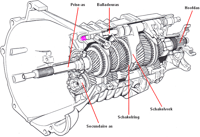
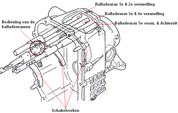
In the image below you can see that the selector shaft can move back and forth. This movement is indicated in pink. The selector shaft operates the shift fork. With the help of the shift ring, the shift fork presses the synchromesh ring against the gear. When shifting to the next gear, the selector shaft moves back so that the shift fork is set to the neutral position. By engaging another gear, the same shift fork is moved by the selector shaft in the opposite direction to engage the other gear (e.g. from third to fourth gear), or a different selector shaft is used to operate the other shift forks.
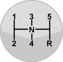
There are several selector shafts in the gearbox. Each selector shaft can engage or disengage two gears. Operating the different selector shafts is done by moving the gear lever left and right. The image below shows the H‑pattern of the gears.
When the driver wants to engage first gear, they will first move the gear lever from the middle (N for ‘neutral’) to the left. The shift rod will engage with the teeth of the selector shaft for first and second gear.
By moving the lever up (towards first gear), the selector shaft is pushed backwards (upwards to the right in the image). The shift fork then connects the gear of first gear to the shaft.
To shift to second gear, the lever must be moved downwards (to neutral). The shift fork disconnects the shaft from the gear. By moving the lever further down, the same shift fork connects the other gear to the shaft; second gear is now engaged. So this selector shaft moves the shift fork between first and second gear.
To shift to third gear, the gear of second gear must first be disconnected from the shaft. For this, the lever must first be moved up again (to the neutral position). Then the lever must be moved to the middle of the H‑pattern. By moving the lever from the left to the middle, the selector shaft for third and fourth gear is engaged. Pushing the lever forwards and backwards will cause the shift fork for third and fourth gear to move forwards or backwards to engage these gears.
When upshifting to fifth gear, the lever is pushed all the way to the right. This engages the selector shaft for fifth gear and reverse. To select fifth gear, the selector shaft is pushed forwards so that the shift fork can connect the gear to the shaft.
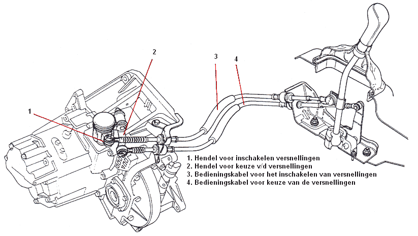
The image shows a shifting mechanism. This cable-operated mechanism is used in a car with a transversely mounted engine block. Because levers 1 and 2 are moved by the pushing or pulling motion of the cables, the shift forks are moved by a so‑called shift tower.
Synchronizer unit:
When no synchronizer unit is used, the gears will either not mesh or will mesh with grinding noise due to the difference in rotational speed. To ensure the meshing of the gears goes smoothly, synchromesh rings are used. The synchromesh rings ensure that the speeds of the shaft and the gear are equal when engaging. All forward gears (1 through 5 or 6) are synchronized, often with the exception of the reverse gear. You will notice that, because the gear will sometimes grind when engaging reverse. In some cases, reverse gears are synchronized as well.
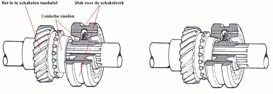
The gears of the speeds that are not engaged rotate freely on the output shaft. Engaging a gear therefore means coupling a freely rotating gear to the output shaft. When a gear is engaged, the speed of the output shaft must match the speed of the gear to be engaged. The synchromesh ring is connected to the output shaft by means of splines and therefore rotates at the same speed as this output shaft. The gear that needs to be engaged has a different speed than the output shaft, and therefore also a different speed than the synchromesh. When the shift fork moves, it takes the synchromesh with it and the conical section of the synchromesh ring will be pressed against the internal conical surface of the gear. The conical sections of both parts are pressed together, causing the friction between the conical surfaces to be equalized. When there is no longer any speed difference between the two gears, the sliding sleeve can be pushed through so that the teeth slide into each other and the gear is engaged without grinding. The synchronizer unit does not only work when engaging gears, but also when shifting up and shifting down.
It is very bad for the synchromesh rings to shift very quickly, i.e. to push the gear lever very hard into a gear. The synchromesh then does not get the time to synchronize. It is therefore best, when shifting, to gently push the gear lever against the resistance and only push it through when it almost slips into gear by itself.
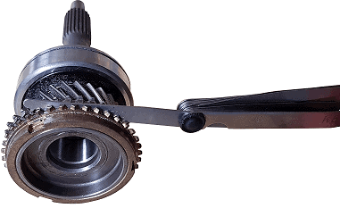
A synchromesh ring is a wear part. During shifting, friction occurs, so the part will wear over time. With normal use, the synchromesh ring can last the lifetime of the car, but with improper use or sporty shifting, the synchromesh rings will wear out prematurely. The distance (3) between the synchromesh ring and the gear in the image below will then become smaller. This is because the synchromesh ring wears at the contact area where it touches the gear. This section is indicated with distance 1.
When the gearbox has been disassembled, the synchromesh rings can be checked for wear. With a feeler gauge the distance between the synchromesh ring and the gear can be measured. The gear concerned must not be engaged while doing this. As a synchromesh ring wears, the distance between the synchromesh ring and the gear becomes smaller.
The manufacturer of the car or gearbox specifies in the workshop documentation what the wear limit of the synchromesh ring is. If the measured value is smaller than the maximum wear value in the workshop documentation, it must be replaced.
Disassembling the gearbox:
This paragraph describes how a gearbox can be disassembled. This gives a good impression of what the inside of the gearbox actually looks like and how the parts in the gearbox can be replaced. This concerns a gearbox of a rear‑wheel‑drive car with a longitudinally mounted engine.
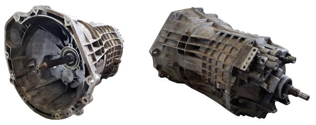
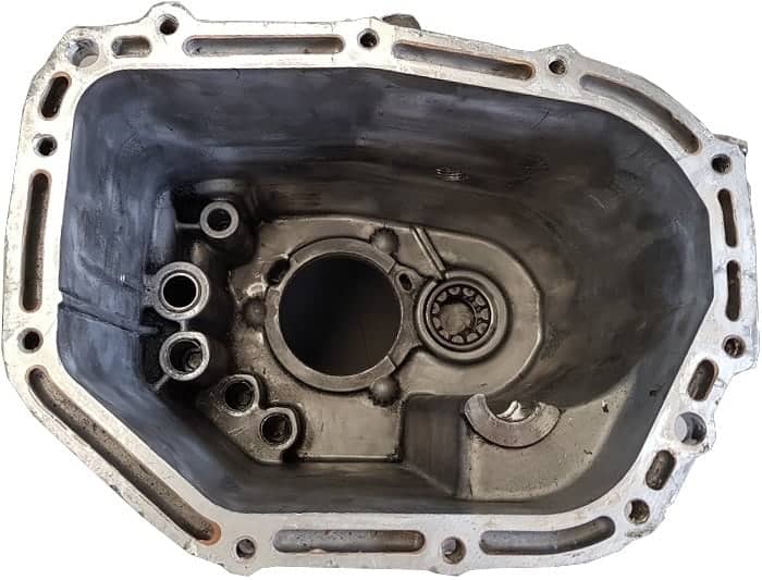
On the illustrated gearbox, a number of bolts at the rear can be removed. Then the rear section can be slid off. Naturally, the gearbox oil must first be drained before any parts are removed.
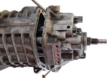
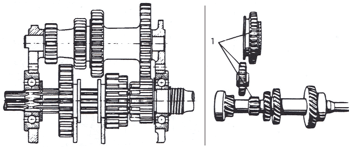
The internal assembly with shafts and gears is attached at the rear. The complete internal assembly comes out of the gearbox housing during disassembly.
On the inside (on the right side of the opening through which the input shaft passes when assembled) the bearing of the secondary shaft can be seen.
On the left side of the input shaft opening, five holes can be seen. In these five holes are the four ends of the selector shafts.
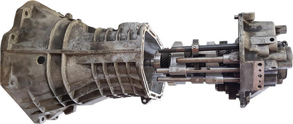
In the image, the input shaft, the gears, and the selector shafts with the shift forks can be seen. When shifting, the relevant selector shaft rotates and moves so that the shift fork operates the synchromesh ring of the gear to engage the gear.
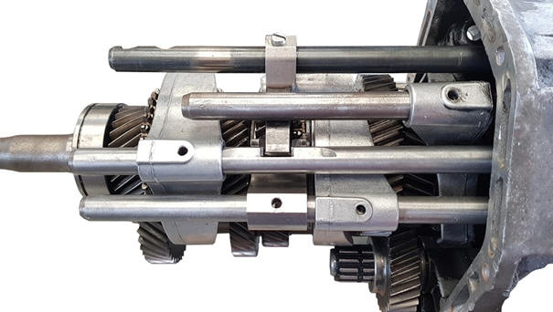
After removing the clamped pins or screws with which the shift forks are connected to the selector shafts, the selector shafts can be slid out. This frees the shift forks. The shift forks can then be slid off the shafts.
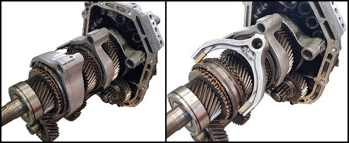
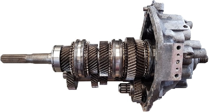
In the image below, it is visible what the gears look like. When gears or synchromesh rings need to be replaced, the shafts must be removed from the other side of the gearbox housing. The gears and the synchronizer unit must be pressed off the shafts. The new parts then need to be pressed back onto the shaft.
To check whether the synchromesh rings are still in good condition, the distance between the gear and the synchromesh ring must be measured. When the distance is greater than the maximum value specified by the manufacturer, the synchromesh ring is worn. The synchromesh ring will need to be replaced. How the measurement must be carried out is described under the paragraph “synchronizer unit” on this page.
Constant Mesh:
In a Constant Mesh gearbox the gears are ‘constantly’ meshed with each other. The gears are mounted on the output shaft and are connected to each other by means of sliding sleeves and dog clutches. In the explanation above, the Constant Mesh gearbox has been discussed throughout.
In the image below, the right‑hand sliding sleeve moves to the right to engage first gear and to the left to engage second gear.
Sliding Mesh:
These are English words for ‘sliding’ and ‘meshing’. In this type of transmission, gears are slid into position to engage a particular gear. This is still used today for reverse gears, but almost never in modern gearboxes, so we will not go into it too deeply. The teeth are straight with a chamfer on the ends. With this type of gearbox you will always hear grinding when shifting, because it is of course not synchronized.
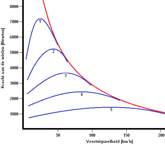
Gear ratios:
The gear ratios in the gearbox must be accurately calculated and designed. In the image below, the vehicle speed can be seen on the X‑axis and the force at the wheels on the Y‑axis. You can see that 1st gear provides a lot of force at the wheels, but ends at a low vehicle speed. Each subsequent gear provides less force at the wheels and a higher speed range.
Click here to go to the Gear Ratios page, where all gear ratios are calculated using the geometric progression and the corrected geometric progression (Jante’s series) with the K‑factor.
The maximum vehicle speed can then also be calculated for each gear.