Introduction:
Measurement is used a lot in engineering. This page covers measurement in relation to automotive technology. In automotive technology, there are many different ways to perform measurements: during development, testing, monitoring processes, and troubleshooting. Once you know how to measure, you only need documentation (wiring diagrams) to determine where to measure.
The most commonly used (electrical) measuring instruments in automotive technology are:
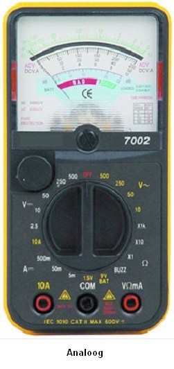
- The multimeter / analog meter: This is used to measure voltage (U), current (I) and resistance (R). The digital multimeter will display the value on the LCD screen, and the analog meter will indicate the measured value on an underlying scale by means of a needle.
- The oscilloscope: With the oscilloscope, voltages are measured that can be recorded along a timeline. This timeline can be set (number of Volts on the Y-axis and the time interval on the X-axis).
Analog meter:
The analog meter (moving-coil meter) consists of a permanent magnet and a moving coil. The current flowing through the moving coil produces a magnetic field. The forces that the magnetic fields exert on each other cause the moving coil (with the needle mounted on it) to rotate. The higher the current (and therefore the magnetic field), the further the needle will deflect.
Advantages compared to the digital multimeter:
- Inexpensive;
- More accurate below 10 Hz (not above that).
Disadvantages:
- Harder to read;
- Relatively slow due to the moving needle.
Digital multimeter:
The digital multimeter is a replacement for the analog meter. The meters are continuously being further developed (in accuracy, speed and functions). The multimeter contains an A/D converter. The analog signal being measured is first processed before it is displayed. This processing depends on the selected function (Volt, Ampere, Ohm, etc.). The digitized signal is then sent to the display. The speed at which this happens is called the “response time”, which can be found in the specifications of the meter. The response time (of the A/D converter) is the time needed to register a change in the input signal. The more expensive the meter, the lower this response time will be.
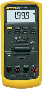
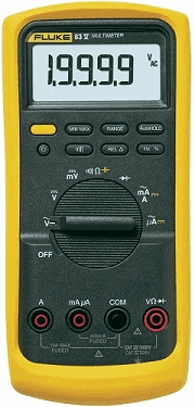
There are digital multimeters with manual and automatic range selection. This is used to set the measuring range. The multimeter in the image below does this automatically. The chapter “Measuring range” is described further on this page.
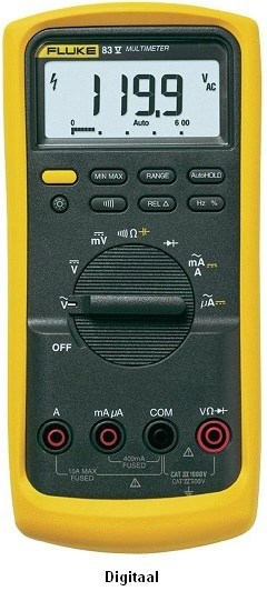
Resolution:
The number of digits displayed by multimeters determines the resolution and thus also the reading accuracy of the meter. The resolution therefore only relates to the screen and not to the measuring range. There are 3½, 3¾ and 4½ digit multimeters. The more digits the multimeter can display, the more numbers are possible (so a more accurate measurement).
3½ digit:
This is a standard multimeter, which in the 200 V range can measure with a maximum accuracy of 0.1 V. If a measurement is taken where the actual voltage is 22.66 V, the meter would display 22.6 V.
3¾ digit:
With this multimeter, the resolution has increased by a factor of 10 and with the same measurement (22.66 V as with the 3½ digit multimeter) it will actually display 22.66 V. That is one hundredth of a Volt more (and therefore more accurate).
4½ digit:
This multimeter has an extra digit available in all ranges. The resolution has again increased by a factor of 10.
Setting the measuring range:
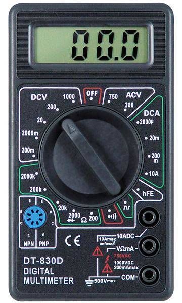
The measuring range of the multimeter below can be set manually. This is necessary to obtain the most accurate possible result with every measurement. When measuring the battery voltage, it is best to choose the 20 DCV option. The battery voltage will, for example, be indicated as 12.41. It is best to choose a measuring range that will be below the maximum measured result. The battery voltage will never be higher than 99 Volts. If a larger range were chosen (of 200 DCV), the battery voltage would be displayed as 12.4 (less accurate). This has to do with the resolution:
| Range: | Resolution: |
| 200 mV | 0.1 mV |
| 2 V | 0.001 V |
| 20 V | 0.01 V |
| 200 V | 0.1 V |
| 2000 V | 1 V |
Examples from this table:
- When measuring a voltage of 100 Volts in the 200 V range, the meter will display 100.1 V. When this same voltage is measured in the 2000 V range, the meter will display 100 V (less accurate).
- When measuring a voltage of 9.188 Volts in the 2 V range, the meter will display 9.188 V. When this same voltage is measured in the 200 V range, the meter will display 9.2 V (rounded, so less accurate).
The most accurate measurement therefore depends on which measuring range is set and what the resolution of the display is. With displays with a low resolution, even with an accurate measuring range, the most accurate voltage cannot be displayed.
With the multimeter shown, the measuring range can only be set manually. The more advanced multimeters have an “Autorange” button, where the meter itself sets the best measuring range (based on its own resolution). Only with simple multimeters can you only select the Volt, Ampere (etc.) range and the measuring range is often a standard 20 V (thus with a resolution of 0.01 V).
Another issue is that there is always a deviation in the meter. When setting too low a resolution, the deviation is the greatest. More about this in the following chapters “Absolute and Relative errors” further down the page.
Calculating the absolute error:
Every multimeter has a certain accuracy. This accuracy can be found in the specifications (in the manual). With this data, the deviation of the measurement can be calculated. Two terms can be calculated; the “absolute error” and the “relative error”. The absolute error represents the voltage in Volts and the relative error is calculated in percent.
Example:
Voltage (U) = 12.55 V
±(0.3% rdg + 1d)
rdg = reading = the value read on the display (the measured value)
1d = 1 digit = the resolution (in the 20 V range 1 digit corresponds to 0.01 V and in the 2 V range to 0.001 V).
The actual voltage is 12.55 Volts. This is measured in the 20 V range.
0.3% rdg is 0.3% of 12.55 V = 0.038 V.
In the 20 V range, 1d = 0.01 V.
The total absolute error is therefore: the reading + 1 digit = absolute error. In numbers: 0.038 + 0.01 = 0.048 V
The final answer including the absolute error is:
U = 12.55 ± 0.05 V.
That means that the measurement lies somewhere between 12.50 and 12.60 Volts.
Cheap multimeters often have a larger deviation than more expensive ones, so the total absolute error is also greater. This now proves that “cheap multimeters” cannot perform accurate measurements.
Calculating the relative error:
When the absolute error is calculated as a percentage of the reading, this is called the relative error. This relative error is usually used when comparing meters.
The relative error of the previous multimeter is: total absolute error / (divided by) the actual voltage x (multiplied by) 100% = the relative error.
In numbers: U = 0.038 / 12.55 x 100 = 0.30%.
The final answer including the relative error is:
U = 12.55 ± 0.3%.
12.55 V minus 0.3% gives an answer of 12.50. Plus 0.3% gives 12.60. This is the same as what was calculated using the absolute error, but now expressed as a percentage.
Measuring with the multimeter:
Voltage, current and resistance are all measured in a different way. How to measure correctly with the multimeter is explained with examples on the page measuring with the multimeter.
Measuring with the oscilloscope:
An oscilloscope (abbreviated as scope) is a graphical voltmeter. The voltage is displayed graphically as a function of time. The scope is also very accurate. The time base can be set so small that signals originating from sensors such as the lambda sensor or actuators such as an injector can be displayed perfectly.
How to measure with the scope is explained on the page measuring with the oscilloscope.