Introduction:
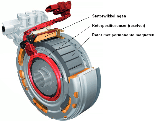
For the operation of the synchronous electric motor it is essential that the correct coils are controlled by the inverter. To determine which coil (U, V or W) needs to be energized, the inverter ECU reads the position of the rotor, which is measured by the rotor position sensor, also known as the “resolver”.
The resolver consists of an outer ring with a number of coils on the inside and a rotating eccentric plate. The distance between the eccentric plate and the coils continuously changes as it rotates.
Resolver signals:
The ECU supplies the resolver with a reference signal. The air gap between a coil and the eccentric creates a high or low sinusoidal AC voltage. With a high amplitude in the red or green sinusoidal signal (see the image below), the air gap between the eccentric and the coil is small.
The resolver operates both when stationary and when the electric motor is running: in both cases the ECU must know the position of the rotor.
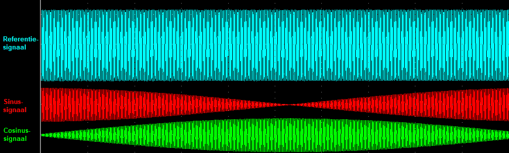
The image below shows the theoretical signals. In reality, the frequency is much higher, making the variation in the amplitude of the sine and cosine signals clearly visible.
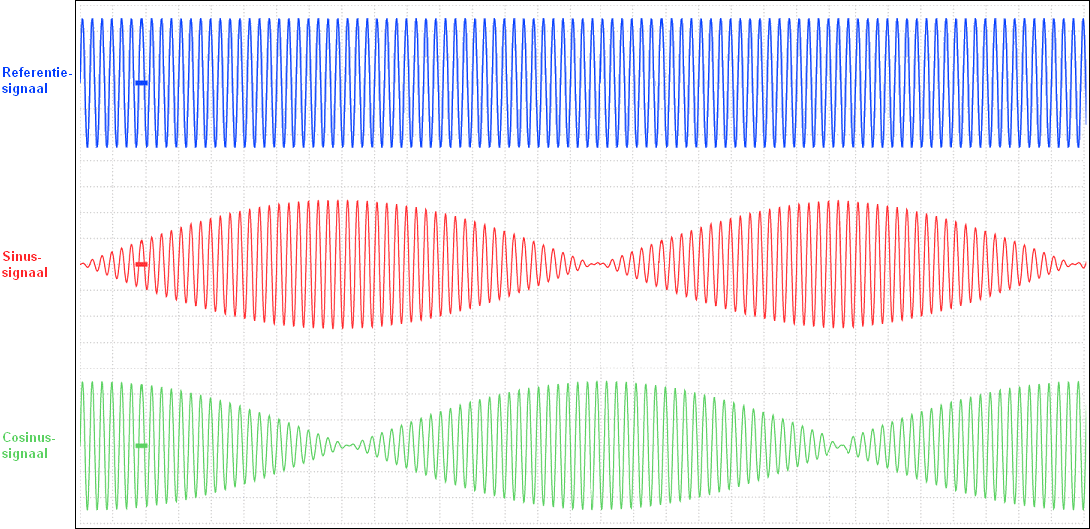
The two images below show an actual measurement on a resolver. Here too we see the reference signal at the top, and below it the sine and cosine signals. The first image is taken at a standstill: the electric motor is not running. The amplitude of the sine signal and the cosine signal remains constant. Based on the amplitude of this AC voltage, the ECU knows where the rotor is when stationary.
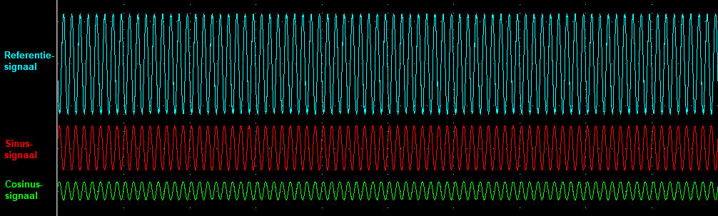
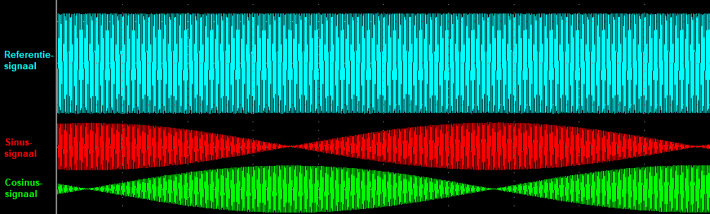
In the next two images, the time per division has been reduced. The frequency of the reference signal on the resolver is unchanged, but the measurement is taken over a longer period of time. As a result, we can clearly see the amplitudes of the sine and cosine signals changing. The first image is measured at a low rotor speed and the second at an increased speed. As the speed increases, the frequency of the sine and cosine signals becomes higher (more signals per unit of time) but the amplitude (the level of the AC voltage) remains constant.
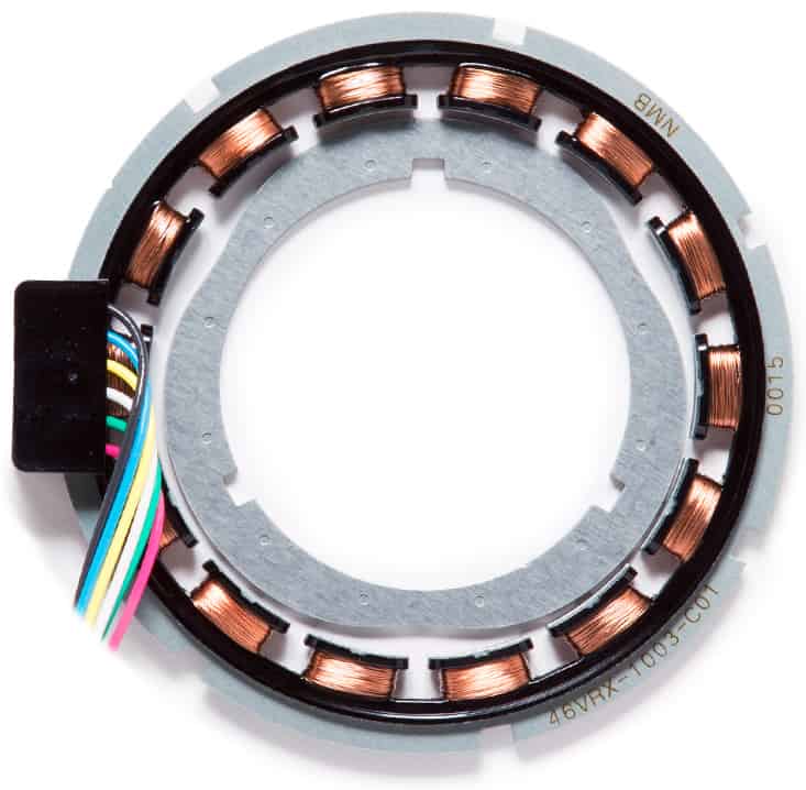
Resolver components:
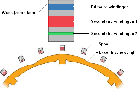
The resolver of the VW E-Golf contains 30 coils connected in series. Each coil in the resolver consists of a soft-iron core with three different windings: primary, secondary 1 and secondary 2.
The primary coil (blue) is supplied with a high-frequency AC voltage.
The number of secondary windings (1 red, 2 green) is different on each coil.
When the lobe of the eccentric plate moves past the coil, the induction in the secondary windings is amplified. Due to the number of turns of the secondary windings 1 and 2 in each coil, this also results in different voltages in the secondary windings. The ECU in the inverter can calculate the position of the rotor based on the voltages of the secondary windings 1 and 2.
The alignment of the resolver on the rotor is extremely precise: many manufacturers prescribe that in case of problems with the resolver, the entire electric motor must be replaced. After (accidentally) disassembling the resolver, or loosening the bolts on the outside of the electric motor housing, the resolver can no longer be reinstalled correctly. In that case as well, many manufacturers prescribe replacing the electric motor.
The exact rotor position of a synchronous motor must be known both at a standstill and while driving. When the sensor is defective, the vehicle can no longer be driven.
For the asynchronous motor, on the other hand, monitoring of the rotor position is not required. Per rotor revolution, the rotor position sensor outputs four pulses. With this measurement, the maximum amount of slip between the rotating magnetic field of the stator and the rotor is monitored. The Hall sensor is often used as the sensor. The Hall sensor sends pulses to the ECU when the rotor turns, but unlike the resolver of the synchronous motor, it cannot take measurements at a standstill. Manufacturers sometimes also choose to use the resolver of the synchronous motor as a rotor position sensor.
Related pages: