Thevenin equivalent circuit:
The Thevenin theorem is a commonly used method for simplifying complex circuits. Any circuit with one or more voltage sources and a number of resistors can be replaced by one voltage source Eth and one internal resistance Rth. The Eth and Rth that are calculated are important for ultimately determining the voltages across the resistors and the current through the circuit.
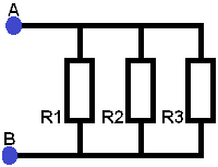
Circuit 1:
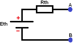
Shown alongside is a Thevenin equivalent circuit. Eth represents the voltage source and Rth the equivalent resistance. Any circuit with multiple voltage sources and multiple resistors can be simplified to this circuit.
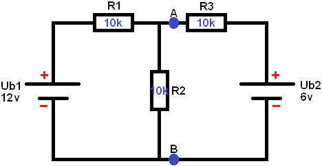
This circuit with 2 voltage sources and 3 resistors is calculated and simplified to the Thevenin equivalent circuit. In the following steps the voltages and currents in the circuit are calculated to determine the voltage UAB (the voltage at points A and B).
Step 1:
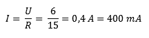
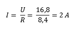
Determine the equivalent resistance of the circuit below in which UB2 is short-circuited. The formulas show the derivation of the equivalent resistance and the current.
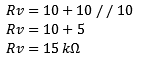
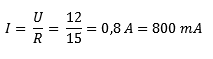
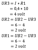
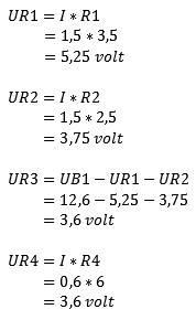
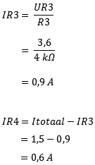
Short one voltage source. In this case Ub2 (see image below). Remove the voltage source from the circuit. From voltage source Ub1 a current of 0.8 A will flow. First the voltage across resistor R1 must be calculated, because the current encounters this one first.
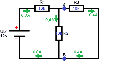
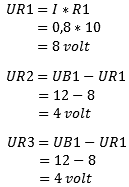
It is important not to calculate UR2 in the same way as UR1, because the voltage UR1 still needs to be subtracted from it. This is because the voltage is lost across the consumers. At the beginning of the circuit the voltage is 12 volts, but when the negative terminal is reached, the voltage must be 0 volts. This is not the case with current! All current that leaves the battery is distributed throughout the circuit and comes back together at the negative terminal of the battery.
Step 2:
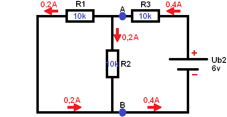
Ub1 has now been removed from the circuit and Ub2 has been put back. Now the equivalent resistance and current as a result of Ub2 need to be determined.
Step 3:
Now it is time to restore the circuit to its original state:
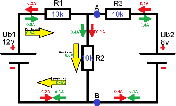
The current direction of both circuits is shown; the green of the first and the red of the second circuit. If the current directions are opposite to each other (the arrows are pointing towards each other), a resulting current will remain.
0.2 A to the right and 0.8 A to the left: this means that 0.6 A flows to the left (by simply subtracting 0.2 from 0.8).
0.4 A to the right and 0.4 A to the left: cancel each other out. The resulting current is 0.
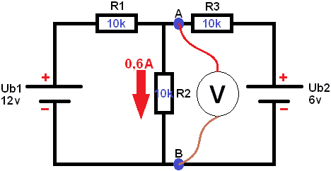
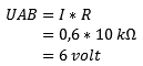
The current through resistor R2 is known. The voltage UAB can now be measured. The voltage UAB is in parallel with R2, so they are the same. In principle, the resulting voltage across R2 is now also being measured: UAB = UR2.
Step 4:
To create a Thevenin equivalent circuit, step 4 still needs to be carried out. UAB open is known. This is also called the open-circuit voltage, Eth or Uth (in this example Eth is used). Eth stands for the Thevenin voltage.
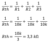
Calculating Rth:
Eth is known. So in the final Thevenin equivalent circuit, Eth and Rth must be indicated:
In the circuit below, the Thevenin equivalent circuit is shown as it is officially intended. Any circuit with one or more voltage sources and resistors can be simplified to this circuit:
Eth = 6 volts
Rth = 3.3 kΩ
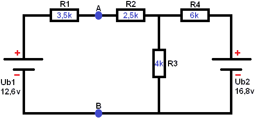
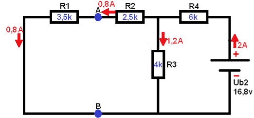
Circuit 2:
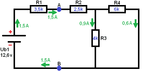
Below is a circuit with 2 voltage sources (Ub1 of 12.6 V and Ub2 of 16.8 V). The voltage UAB must be determined (that is, the voltage at the blue dots). In the following steps the voltages across the resistors and the currents throughout the circuit are calculated. Based on that, the voltage across A and B can again be calculated.
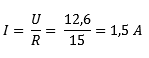
Short 1 voltage source. In this case Ub2. Remove the voltage source from the circuit. From voltage source Ub1 a current of 1.5 A will flow. First the voltage across resistor R1 must be calculated, because the current encounters this one first.
Lorem ipsum dolor sit amet, consectetur adipiscing elit. Ut elit tellus, luctus nec ullamcorper mattis, pulvinar dapibus leo.
Step 2:
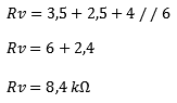
Determine the equivalent resistance of the circuit below. Here, Ub1 has now been removed from the circuit and Ub2 has been put back. In this case the equivalent resistance is again
Step 3:
Now it is time to restore the circuit to its original state:
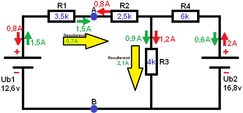
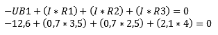
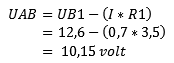
With this data, the voltage UAB can be calculated. A current of 0.7 mA flows through resistor R1 of 3.5 kΩ. Because the left part of the circuit (the part of Ub1) is a closed circuit, UAB is calculated using the voltage of Ub1. Ub2 does not play a role now, because this is a different closed loop. This is easy to see by applying Kirchhoff: All voltages in a closed circuit are equal to 0. We can prove this:
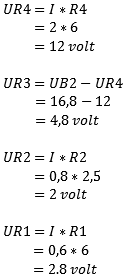
Calculating voltage UAB:
Related pages: