Breakout box:
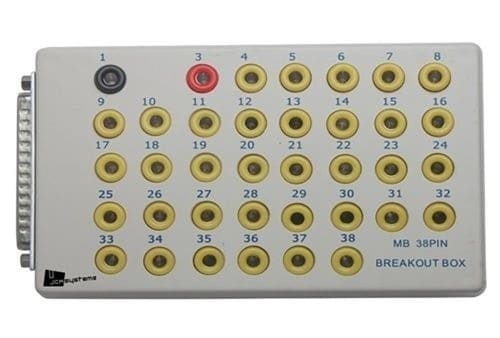
A breakout box is a tool used to perform measurements. With the aid of the breakout box, plugs do not need to be opened and cables do not need to be stripped in order to take measurements. Each wire has its own measuring point in it. The image below shows an example of a breakout box.
When voltages need to be measured at the control unit, this is only possible when the connector is plugged in. With a disconnected connector, first of all you can never perform proper measurements, and second, the engine will not be able to run when this concerns the engine control unit. For this reason, unfortunately people sometimes pierce into the cables. By sticking the test probe into the wire, the voltage on this wire can be measured. However, the insulation is damaged, so months or even years later a new fault may occur due to excessively high contact resistance or a broken wire; moisture can now easily enter the cable. This can be prevented with a breakout box. Reputable workshops and well-trained specialists will therefore never pierce the cables, but use a breakout box.
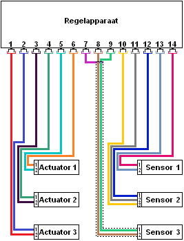
In the diagram on the right, a control unit is shown that is connected to various sensors and actuators. At this point there is no breakout box yet, but a properly functioning engine management system.
The actuators (left) and sensors (right) have two or more wires per connector. Usually these connections are:
- positive (12 or 5 volts);
- ground;
- signal or control.
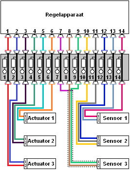
To be able to perform measurements on the sensors and actuators, you can check whether there is enough space in the component’s connector to insert the pins of the multimeter or the oscilloscope. Often the connectors are watertight and you cannot reach the contacts without damaging the cable. Stripping the cable or piercing into it is obviously not advisable! To still be able to carry out proper measurements, a breakout box can be placed between the control unit and the sensors / actuators. This can be seen in the diagram below.
The connector of the control unit in the diagram on the right is connected to the breakout box. The connector of the breakout box is in turn connected to the control unit. In this way, the sensors and actuators are still connected to the control unit, so the entire system will continue to function without faults. Inside the breakout box, the wires are simply passed through.
In the breakout box there are multiple connection points; in the image below these connections are shown as circles above the numbers. The numbers of these connections correspond to the pin numbers of the control unit. Each wire in the control unit connector therefore has its own measuring point in the breakout box. Between the wires and the connection points, resistors are visible. These resistors are often around 500 Ohms and serve to protect the measurement that may be performed incorrectly. Without these resistors, the chance of the control unit being blown is considerably higher.
Example of a measurement: When the signal from sensor 1 needs to be measured, we are interested in the voltages on pin numbers 1 and 2 of the sensor connector (these numbers are written in small print next to the wires).
The pink wire is connected to pin 1, and the blue wire is connected to pin 2. When the connector is insulated, the voltage must be measured further along the circuit, namely at the control unit or at the breakout box. The pink and blue wires run to pin 13 and 14 of the breakout box. The voltages measured here on pin 13 and 14 are therefore the same as if the measurement were taken directly at the control unit connector or directly at the sensor connector.
In the example above, an elongated breakout box with 20 connections is shown. In reality, breakout boxes are often square or rectangular, and sometimes there are more than 100 connections on them. Often, several connectors can be plugged into one breakout box. In that case, pay close attention to the coding. If, for example, the coolant temperature sensor needs to be measured, you must first determine to which control unit and therefore which connector this sensor is connected (e.g. T60). The breakout box will then also show other designations, for example T45 and T32; these are other connectors. The correct connector can be found in the wiring diagram.
Reading an electronics diagram:
To clarify the explanation below dealing with measurements, all terms, designations and abbreviations of the relevant electrical diagram are explained. The diagram below is of the “waterfall” type. This means that the positive supply lines come from the top and the ground is at the bottom. The current in fact flows from top to bottom. Terminal 30 is the constant positive, terminal 15 is the switched positive. A supply voltage appears on this terminal when the vehicle ignition is switched on. Terminal 31 is the battery ground.
The diagram below is part of the fuel system with a fuel pressure sensor and the fuel delivery pump with the float unit:
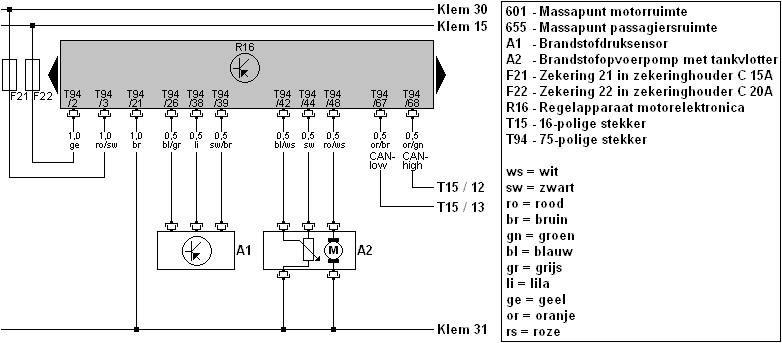
Fuses F21 and F22 are located in fuse holder C. This fuse holder is located in the dashboard, on the left-hand side of the driver. The control unit (called R16) is the engine control unit. It is located behind the engine compartment, at the height of the wiper mechanism. In the diagram, two black arrows are shown to the left and right of the control unit; these indicate that the control unit is larger than shown in the illustration. It can also be seen that the pin numbers are not in a logical order; starting at pin 2 and 3, followed by 26, 38 and 39. On the connector of the control unit, however, the pin numbers increase sequentially, starting at pin 1 up to pin 75. All wires to and from the sensors and actuators are connected to these terminals of the control unit.
Each wire has its own pin number and colour. The explanation of the colours can be found in the legend. The wire ro/sw means that it is a red wire with a black stripe (and not the other way around).
Furthermore, the components such as the sensor and the pump are indicated with a code (A1 and A2). At A2 there are two wires going to ground; one from the variable resistor of the tank float and one from the electric motor of the pump.
On the right-hand side of the diagram, the CAN bus wires with CAN high and CAN low can also be seen. These wires run to connector T15, terminals 12 and 13. Connector T15 is located elsewhere in the car; this location can be found in the workshop documentation. In this case, it concerns the connector on the Gateway. This diagram is used in the following examples, in which measurements are carried out using the multimeter and the oscilloscope.
See also the page: Reading wiring diagrams.
Measuring on the breakout box with a multimeter:
The diagram is shown again below. In this case we want to check the supply voltage. From the diagram we can read that on connector T94 of engine control unit R16, pin 3 carries the constant positive from the battery:
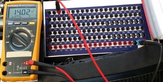
In the image below, a measurement on the breakout box is carried out with the multimeter. The positive probe (the red one) of the multimeter is connected to terminal 3 of connector T94 (T94 is shown in orange). The ground is measured via the blue terminal; this is the central ground of the breakout box itself.
From the diagram it can be seen that the control unit is grounded via the wire and pin 21. When the negative probe is placed on pin 21 and the voltage is 0 volts, while via the central ground the multimeter indicates 14.02 volts, it may be that the ground wire between pin 21 and the grounding point on the bodywork is interrupted. That would be an explanation when a fault code is stored concerning an interruption in the ground, or when the control unit cannot be switched on.
Measuring on the breakout box with an oscilloscope:
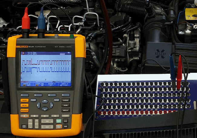
With the oscilloscope, the voltage can be measured over time. This can be useful, among other things, when measuring CAN bus signals. We will do this below. In the diagram it can be seen that the CAN bus wires are on pin 67 and pin 68 of connector T94 on control unit R16:
The two probes of the oscilloscope are therefore connected to pin numbers 67 and 68 of the breakout box. The grounds of these probes are connected to any suitable ground point on the car. After the scope has been set up correctly, the following image is visible:
With the aid of these examples, a clear picture can be formed of how the breakout box can be used in practice. The voltages can be measured with both the multimeter and the oscilloscope. The disadvantage is that the currents cannot be measured.