Introduction:
A tangle of wires runs through the car. These wires run very close to metal in many places. A wire can become damaged and chafe through, causing the conductive material to come into contact with the metal of the bodywork. This can cause a short circuit. There can also be countless other reasons why a short circuit can occur, e.g. incorrect connection of wiring, internal short circuit in components, and moisture entering connectors and control units. A fuse with too low a rating, or connecting too many consumers to a single positive wire can also lead to a blown fuse.
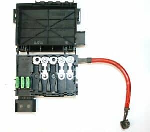
Fuses are used as protection against overload and short circuit. We find fuses in different places in the car. Usually they are all located in a central position in the dashboard on the driver and/or passenger side behind the glove compartment, but sometimes we also find fuses in a plastic holder on the battery or in a fuse box in the trunk.
On this page we will look in more detail at the types of fuses in passenger cars and the ways to trace defective fuses. Diagnosing by measuring the voltage drop across a fuse to determine the amount of current is described on the page: measuring the voltage drop across fuses.
Nominal value:
All fuses have a nominal value, in other words: a maximum permissible current; this is indicated on the top of the fuse (e.g. 10 Ampere). This means that a current of up to 10 A can flow through it. When a higher current than 10 A flows through it due to overload, an electrical fault or a short circuit, the conductive contact in the fuse is heated to such an extent that it eventually melts. The circuit is now interrupted.
No more current can flow through that circuit, preventing damage to wires and components due to the short circuit. Before replacing the fuse, the cause must first be known. A fuse does not blow for no reason. Below are some causes of a defective fuse:
- An incorrect fuse may have been fitted: a 10 A instead of a 20 A, for example;
- Too many consumers are connected to one fuse, e.g. with retrofitted accessories. The fuse and also the wiring are not designed for this. Therefore, do not simply replace the fuse with one of a higher rating, because there is a high risk that the wiring will be overloaded;
- The electrical component behind the fuse has a problem: think of worn / stiff-running bearings in the interior fan, or a high friction resistance in the window rubbers causing the window motor to be more heavily loaded. In both cases this is accompanied by a higher current, which may be close to the nominal value;
- There is an “occasional” short circuit, such as two worn wires in a door or trunk gaiter. When opening and closing, the conductive parts of the two wires touch each other, resulting in a short circuit.
If the fuse keeps blowing after it has been fitted, there may be a short circuit. A test lamp can be used to locate the short circuit. The page tracing a short circuit with a test lamp describes how this works.
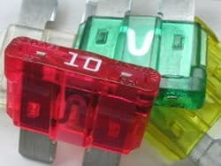
Types of fuses:
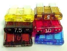
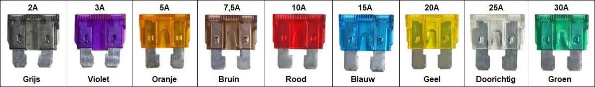
In passenger cars we usually find blade fuses. The blade fuses come in six different sizes. The different fuses are shown in the image below. The actual size may differ from how they are shown below. The legend lists the dimensions in millimeters and the nominal current ratings.
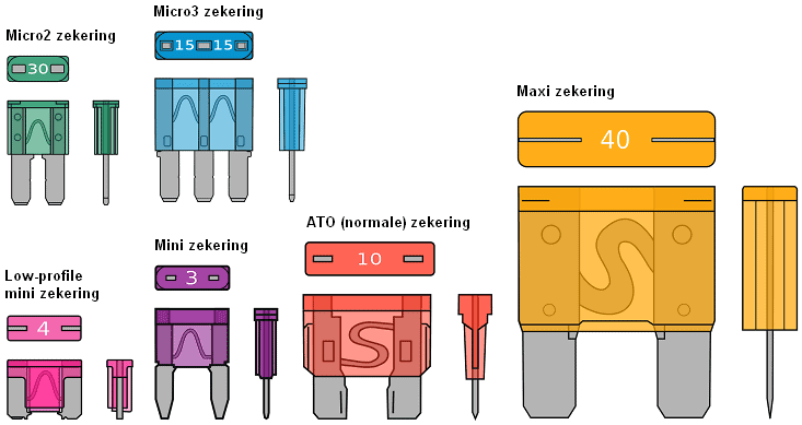
Dimensions (l*w*h):
- Micro2: 9.1 × 3.8 × 15.3 mm
- Micro3: 14.4 × 4.2 × 18.1 mm
- Low-mini: 10.9 x 3.81 x 8.73 mm
- Mini: 10.9 x 3.6 x 16.3 mm,
- Normal: 19.1 x 5.1 x 18.5 mm
- Maxi: 29.2 x 8.5 x 34.3 mm
Current ratings (A):
- Micro2: 5, 7.5, 10, 15, 20, 25, 30
- Micro3: 5, 7.5, 10, 15
- Low-mini: 2, 3, 4, 5, 7.5, 10, 15, 20, 25, 30
- Mini: 2, 3, 4, 5, 7.5, 10, 15, 20, 25, 30
- Normal: 1, 2, 3, 4, 5, 7.5, 10, 15, 20, 25, 30, 35, 40
- Maxi: 15, 20, 30, 40, 50, 60, 70, 80, 100, 120
Below are some more types of fuses that we encounter in passenger cars. Cartridge fuses are mainly found in Japanese and Korean cars, glass fuses are often used in retrofitted positive cables for amplifiers. Ceramic (“stone”) fuses are often found in older cars. High-power fuses can be found both in the fuse boxes in the interior and in a small box on top of the battery. The high-power fuses are used, among other things, for the cooling fan due to the high electrical power.
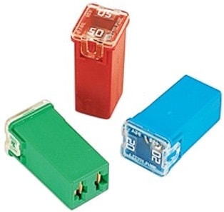
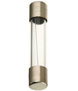
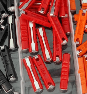

The appearance of the fuses may differ slightly from the image above. For example, each manufacturer uses just a slightly different shade of green, and some use a colored plastic housing over a high-power resistor, while others choose to make the fuse element visible and stamp the nominal value into the metal.
Checking fuses:
When consumers in the car stop functioning, we usually first check the condition of the relevant fuse.
- On the road, you can use the fuse chart (usually located in the fuse box as in the images below, or on the sticker in the cover, or in the owner’s manual) to find which fuse belongs to which consumer;
- In the workshop you can find the explanation in the workshop documentation or wiring diagrams (or a combination of both).
Be careful with pulling fuses out one by one. Some consumers must be connected to a power source. Removing them may cause a (harmless) fault, the digital or analog clock on the dashboard may reset, etc. When measuring equipment is available, it is better to trace the defective fuse using measurements rather than visually inspecting the fuses after removing them. The same applies when tracing a parasitic draw, where some people pull fuses to see which consumer is causing the quiescent current disturbance.
Measurement with the multimeter (1):
With the voltmeter we can measure the voltage on both conductive sides of the fuse with respect to ground. With a fuse that is in good condition we will measure almost the same voltage on both sides. In this case this voltage is 13.2 volts.
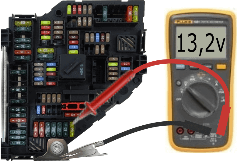
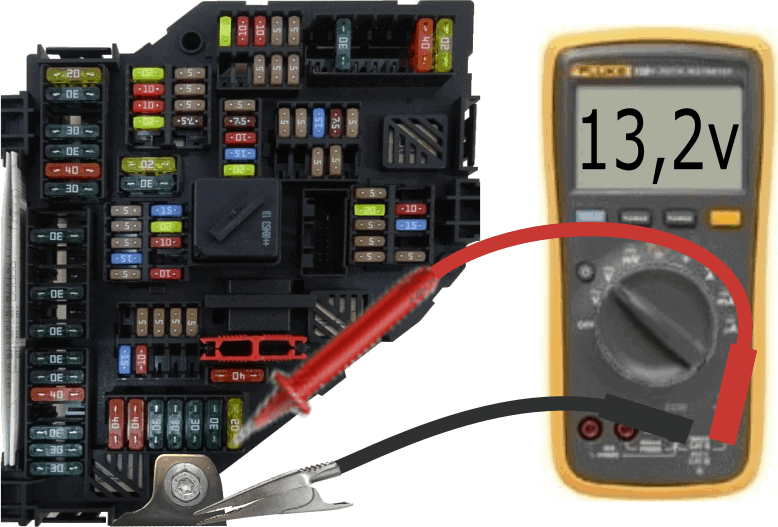
Because the voltage is the same on both sides of the fuse, we know that it conducts properly. The voltage from the positive terminal of the battery is therefore correctly passed on to the consumer.
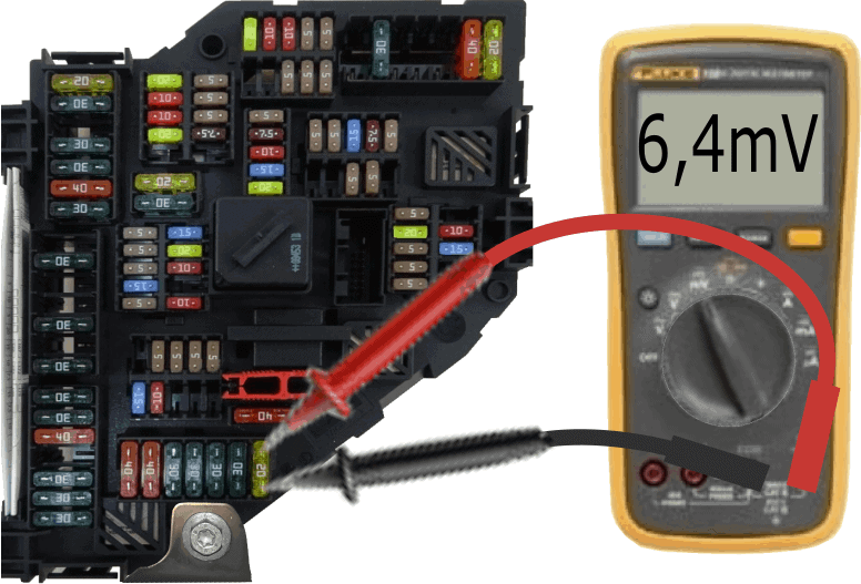
We can also measure the voltage difference across a fuse. When the consumer to which the fuse is connected is switched off, no current flows, of course. The voltage difference is then 0 volts.
With a switched-on consumer, current flows from the fuse to the consumer. Due to the (very low) internal resistance of the fuse, a small amount of voltage is also taken up. We lose this voltage, but it is fortunately minimal. In the image we measure a voltage difference of 6.4 millivolts, or: 0.0064 volts.
In the table on the page “voltage drop across fuses” we can see that a current of approximately 2 Ampere flows through the fuse to the consumer.
This measurement can be useful when you are looking for a parasitic draw.
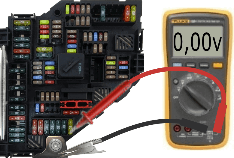
When we are dealing with a defective fuse, we will measure the system voltage on one side (13.2 volts in the example) and 0 volts on the other side. The voltage is therefore not passed through the fuse to the consumer. The measurements on the defective fuse are shown in the image below.
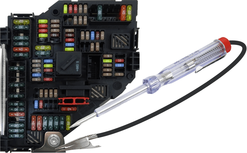
Measurement with the test lamp (2):
A quick way to check the fuses is by using a test lamp. The test lamp consists of a pointed tip (with which the contact points on the fuse are measured), a housing containing a small bulb (tube bulb or LED), and a ground wire with a crocodile clip at the end. We attach the crocodile clip to a good ground point and then go along the fuses one by one with the positive side. On all contact surfaces of the fuses that have voltage, the lamp in the housing will light up. The exact voltage level is not important in this case: there is either the vehicle system voltage (between 11 and 13.8 volts) or 0 volts. In the latter case, the test lamp will remain off.
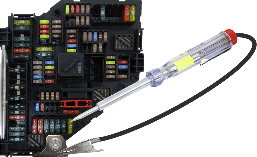
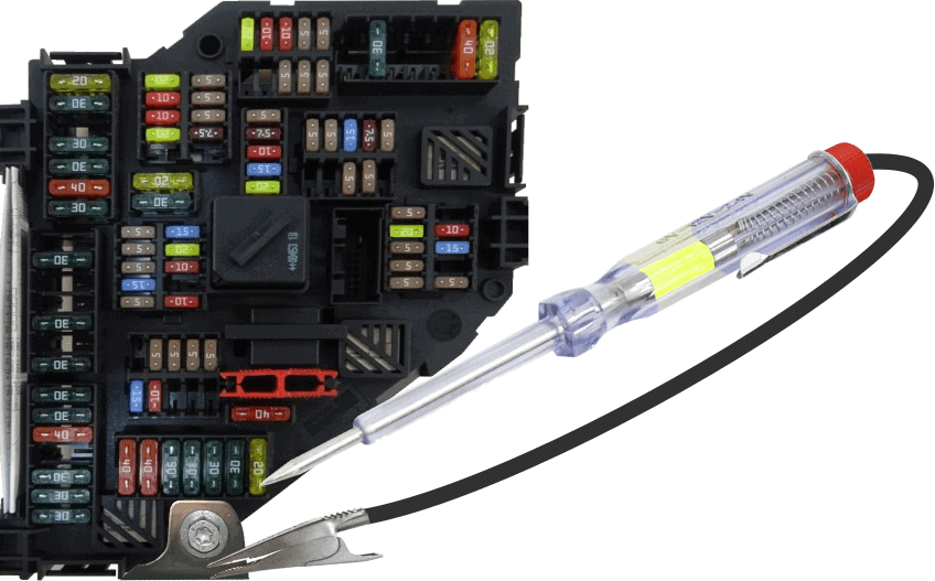
In the following image we see that the test lamp does not light up. It does on the top contact, though. That means this fuse is defective.
If the test lamp does not light up on either side of the fuse, there is probably no voltage on the fuse. This may be because the ignition of the car is not switched on, or because the load is not being supplied with voltage. In the latter case we can pull the fuse out without causing faults and check it visually or with an ohmmeter.
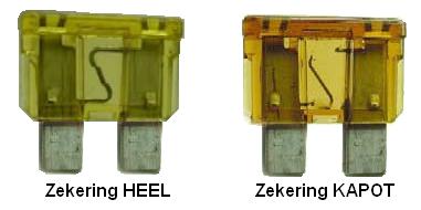
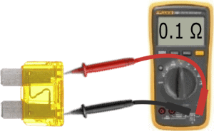
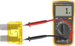
The resistance measurement on a fuse is shown in the two images below. The resistance of a good fuse is about 0.1 Ohm (very low). With a defective fuse there is no connection between the two test leads and the resistance is infinitely high. The ohmmeter will indicate this as OL or as 1.
Practical situation with a defective fuse:
Everyone who drives, owns, or works on a car can encounter this: a fuse has blown. As described earlier, a fuse does not fail for no reason. Usually something is wrong: there is a short circuit in an electrical consumer, in the wiring or the connectors, or there is an electrical overload caused by a mechanical problem. In this paragraph we will look more closely at a practical situation.
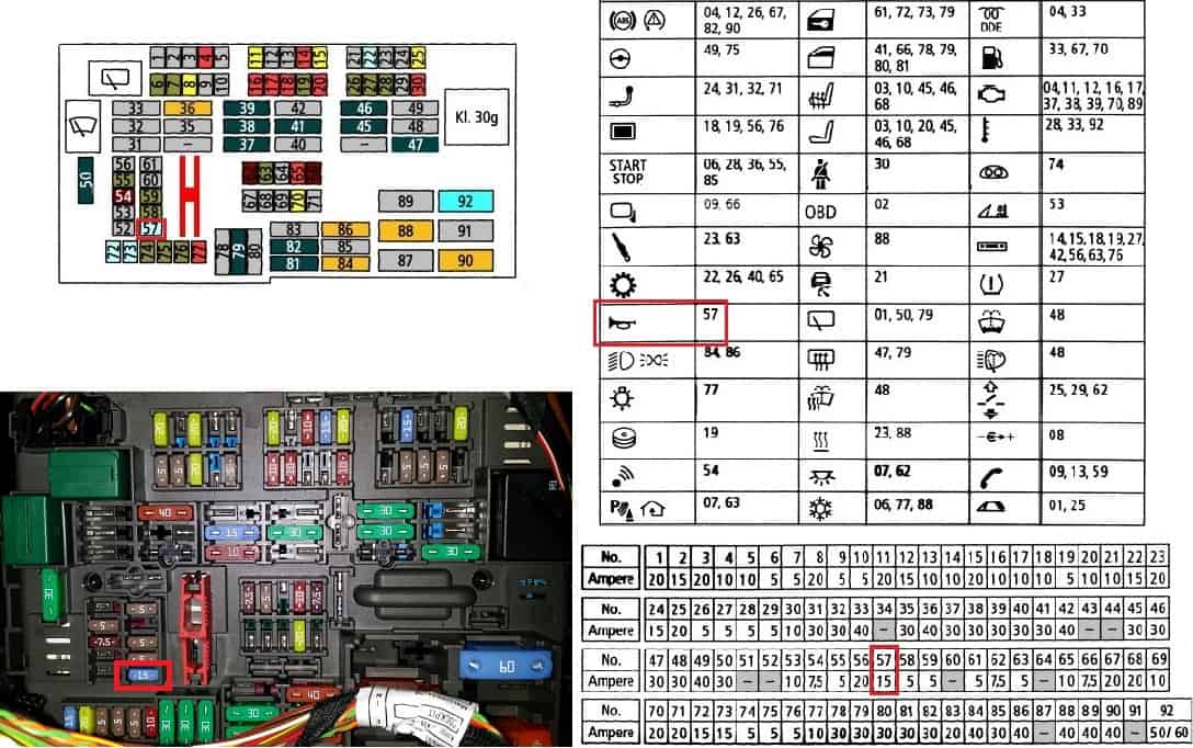
The following problem has occurred: the horn no longer works. When the horn switch (usually the airbag module in the center of the steering wheel or on the indicator stalk) is pressed, nothing happens. First, we look up the fuse chart and position description in the service booklet. In the image below the following is shown:
- top left: positions of the fuses, indicated with numbering from 1 to 90;
- top right: the components the fuses are for. An explanation of these icons is usually also given on a page;
- bottom right: the nominal fuse ratings;
- bottom left: a photo of the fuse box.
Because we have a problem with the horn, we look it up in the overview and in the fuse box. The correct fuse is outlined in red. After replacing the correct fuse (obviously with a 15 A fuse), it blows immediately when the horn is operated.
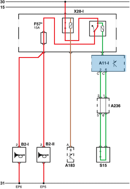
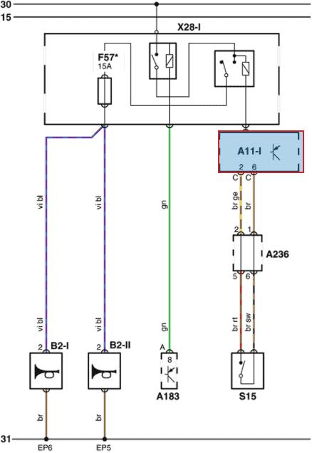
In the workshop the electrical diagrams can be consulted to see how the horns are wired. In the following diagram we see the current circuit of the horn:
- from terminal 30, via the ignition switch A183, the power supply (terminal 30) for the horn relay is energized;
- the horn relay (top right) switches on as soon as switch S15 closes (this is the horn switch operated by the driver);
- When the horn switch is operated, a current flows through the relay coil and the main current is switched on. The current flows via fuse F57 to both horns (B2-I and B2-II).
Because the fuse blows immediately as soon as the horns are switched on, there is presumably a short circuit. By connecting a test lamp across the fuse we can confirm this:
- if the lamp glows dimly with the horns switched on, there is a series circuit and not a short circuit;
- a brightly burning test lamp indicates that there is a short circuit: the test lamp receives a direct power and ground and burns at 12 volts, i.e. at full power.
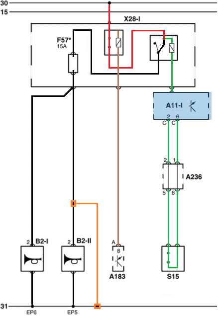
In the two diagrams below two situations are shown: the current flow in a properly operating system and in the event of a short circuit.
- with the ignition switched on (via ignition switch A183), the horn relay is supplied with voltage at pin 30. The horn switch is pressed and the control-current section of the horn relay is energized (green). The main current (red) now finds its way via the relay (output terminal 87) and fuse F57 to the two horns (B2-I and B2-II). The horns are switched on and produce a sound;
- now there is a short circuit. The positive wire of the right-hand horn (B2-II) is connected to ground. There is now a direct connection between the positive (relay output) and ground. To prevent the current from rising to hundreds of amperes, which would damage the wiring and components, the fuse interrupts the positive circuit when the 15 A is exceeded.
In reality, the short circuit could be a chafed positive wire that comes into contact with the bodywork of the car. This can happen after the wiring harness has been refitted incorrectly into its clips/holders after removal of the bumper and front panel. Or after a collision, where the wiring has become pinched.