Introduction:
The road-holding and handling of a car largely depend on the wheel geometry. The term “wheel geometry” refers to all wheel and steering knuckle angles discussed on this page. When a car is being designed, its wheel geometry is thoroughly checked. When, for example, the first version of the Mercedes A‑Class was tested, it turned out that this car could roll over during the slalom test. After these dramatic test results, the wheel angles and the stabiliser action were adjusted until this baby Benz was equal to larger vehicles. The anti-roll bar has a major influence on the car’s handling and is described in a separate chapter.
Wheel alignment:
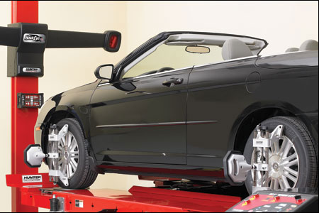
It is important that all wheel angles are correctly adjusted, such as the toe and camber. When repairs have been carried out, such as replacing a track rod, removing/refitting a control arm or the subframe, there is a very high chance that the alignment will no longer be correct. Even after a collision with another car or hitting a kerb, the alignment may be off. If the wheel is visibly tilted under the car, there will be a problem with a bent control arm or track rod. These parts must therefore be replaced!
The car will then need to be aligned. Alignment is done on a special alignment bench, where the computer, with the help of sensors mounted to the wheels, can see the exact angles so everything can be set precisely. Every make and model has specific alignment settings. Lowered cars also have different settings compared to similar cars with a standard suspension.
It may happen that the target values cannot be reached and that the readings lie outside the tolerances. If the front camber cannot be corrected (if it stays in the red), there is a good chance that the shock absorber is bent. In a collision, or when hitting a kerb hard, the weakest point of the MacPherson suspension will bend: the piston rod of the shock absorber. The steering knuckle (with the wheel bearing in it) can also become bent.
If the wheels are not aligned after a suspension repair or a small impact with the kerb, this will be noticeable in several ways:
- The steering wheel is crooked when driving straight ahead.
- The car pulls to one side of the road and constantly has to be corrected by turning the steering wheel.
- Directional stability is poor and changes with every irregularity in the road surface.
- Excessive tyre wear, often irregular: the inside of the tyre still has 4 mm and the outside is bald.
A page about the procedures carried out during wheel alignment will be added soon…
The topics below give an overview of all types of wheel angles that can be adjusted on (most) cars.
Toe:
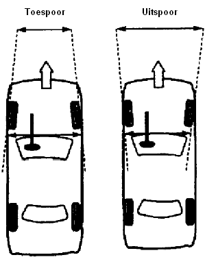
Toe is the direction of both the front and rear wheels. Toe is adjusted by making the track rods on both sides slightly longer or shorter. Space C in the illustration then becomes larger or smaller. Track rod end F then moves inward or outward, changing the wheel angle.
If the wheels point slightly towards each other when stationary, this is called toe-in, and if they point slightly away from each other, this is called toe-out. While driving, the wheels will come into the straight-ahead position. Toe-in and toe-out are often also referred to as “Toe-in” and “Toe-out”.
Cars with rear-wheel drive are set with toe-in at the front axle. While driving, the wheels are pulled outward, bringing them into the straight-ahead position. Cars with front-wheel drive are usually set with toe-out. While driving, the wheels are pulled inward, bringing them into the straight-ahead position. The tolerance here is only a few degrees. In the illustrations it is shown in an exaggerated way, but in reality it is not easily visible. Special alignment equipment is required to detect this.
Camber:
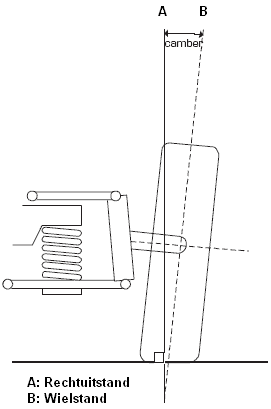
Camber, also called “wheel camber” or “sturz” (German), is the tilt of the wheel relative to the road surface. Camber is measured from a line that is perpendicular to the horizontal road and is expressed in degrees. Camber can be positive or negative. With positive camber, the top of the wheel is further outwards than the bottom (see illustration), and with negative camber it is the other way round; the top of the wheel is further inwards than the bottom.
Negative camber improves cornering grip and stability. That is why lowered sports cars also have a greater negative camber than cars with a standard suspension. A wheel with negative camber tends to run inwards and therefore pushes the wheel inwards. By setting the left and right sides equally, the car will continue to track straight, but tyre wear on the inside of the tyres will increase.
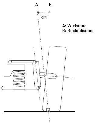
KPI (King Pin Inclination):
KPI, also called steering axis inclination, is the angle between the line through the steering knuckle pivot points and a line perpendicular to the road surface. KPI and caster (next topic) force the front wheels into the straight-ahead position. This effect occurs because, due to the inclined position of the steering axis, the car is lifted slightly when the wheels are turned. The car’s own weight ensures that the wheels are forced back into the straight-ahead position. Impacts from the road surface are also transmitted less harshly to the steering. When the KPI changes, the camber will also change.
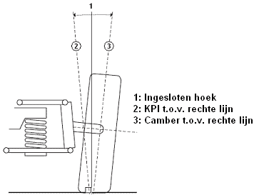
Included angle:
The included angle, also called Included Angle or Gabelwinkel, is not a separate wheel angle, but a supplement to the existing concepts KPI and camber. The included angle can be determined by adding together the values of both angles.
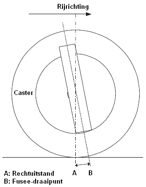
Caster:
Caster, also called “longitudinal steering axis inclination” or “trail”, is the angle between the centre line through steering pivot point B and a vertical line on the road through the centre of the axle A. Caster is always positive.
Caster provides directional stability, because the wheel wants to align itself with the direction of travel when driving straight ahead. You can compare this with the front fork of a bicycle, which also always leans forwards. If the wheel were positioned vertically under the frame, you would lose control of the handlebars over a big bump. If you turn the handlebars backwards, you will also see that they rotate back with the wheel pointing forwards. With a car this principle is the same; by placing the front wheels under the car at a forward angle, the car’s road-holding improves and the steering will automatically return to the straight-ahead position while driving.
When designing modern cars, a large caster angle is often used. The advantage is a very positive driving characteristic. A possible disadvantage of a large caster angle is that the steering effort becomes heavier, but with modern power steering this is not a problem.
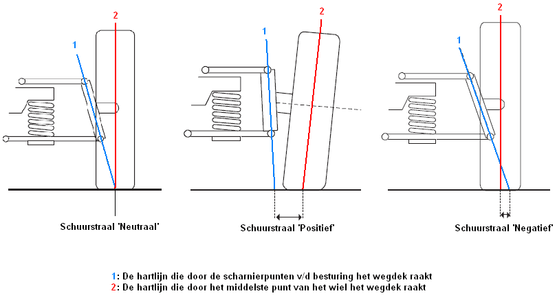
Scrub radius:
The scrub radius, also called Scrub Radius or Lenkrollradius, is the distance between the point where the wheel centre line touches the road surface (the wheel contact point) and the point where the line through the steering pivot points touches the road surface (the steering point). The scrub radius determines the extent to which the height of the front wheels changes when steering and is partly responsible for the straight-line stability of the car.
- If the steering pivot point (blue line) coincides with the wheel contact point (red line), the scrub radius is zero. This is also called a “neutral scrub radius” or “centerpoint steering”.
- If the steering pivot point (blue line) lies outside the wheel contact point (red line), the scrub radius is positive.
- If the steering pivot point (blue line) lies inside the wheel contact point (red line), the scrub radius is negative.
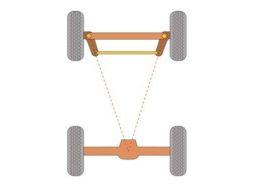
Ackermann principle:
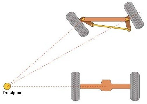
In the illustrations below you can see that the lines from the front wheels converge at the common turning point. If the wheels were turned by the same angle (i.e. both wheels turned by exactly the same angle), the lines from the wheels would run parallel to each other to infinity. They would never meet at the common turning point M. Therefore, the steering characteristics in this situation would be very poor.
This whole principle is called “toe-out on turns”. All modern cars are designed with this characteristic. On slippery surfaces, e.g. the floor in a parking garage, you can hear the tyres squeal when steering. That is caused by this principle. The inner wheel, which turns at a larger steering angle than the outer wheel, will experience some slip.
When driving straight ahead, all wheels are in the straight-ahead position. The extended centre lines of the steering arms intersect at the midpoint of the rear axle.
When cornering, the inner front wheel will turn further than the outer one. This is because the steering arms are positioned at an angle, causing the inner wheel to turn further. When the steering is at full lock, the angled wheel position will also be clearly visible. This construction improves the driving characteristics.
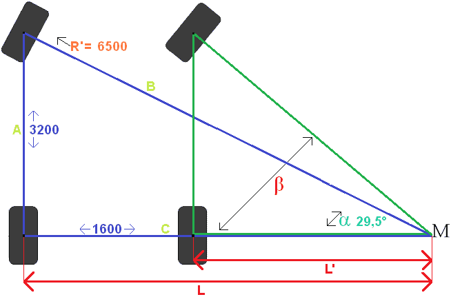
Steering angle:
The steering angle of a vehicle can be calculated on the basis of a number of vehicle data. The illustration below shows the calculation of angle α. Calculating angle β is the next step.
On the page toe-out on turns, the calculation for this illustration is explained in great detail.
Roll centre:
An important concept in suspension is the “roll centre”. The position of the roll centre plays a major role in the driving characteristics. The position of the roll centre is determined by the position of the control arms. This is a very important concept when designing a chassis. Lowering the vehicle also affects the roll centre. Click here for more information about the roll centre.