Introduction:
ABS (short for Anti-lock Braking System). As early as 1961, tyre manufacturer Dunlop successfully experimented with ABS on the Ferguson P99 Formula 1 racing car. That was about fourteen years before anything similar was introduced on ‘normal’ cars. Nowadays all new cars are equipped with ABS.
The purpose of ABS is to make use of the maximum adhesion between tyre and road surface while driving. At the same time, ABS also ensures that driving stability is maintained. This includes:
- Steering stability: when ABS is activated, the vehicle remains steerable. With a skidding wheel the vehicle will slide on in one direction and steering movements can no longer be transferred to the road surface.
- Directional stability: with a locked wheel the vehicle can take a different course. A locked rear wheel, for example, can cause the vehicle to rotate around its axis so that it ends up backwards on the road.
Operation:
The braking system is responsible for decelerating the wheels. Under no circumstances may the wheel lock, because then it will lose grip on the road surface. The wheel will then slide over the asphalt, which also means that steering movements can no longer be transmitted. In that case the vehicle is unsteerable. The ABS system prevents the wheel from locking.
At the moment the wheel is about to lock, the ABS system ensures that the brake pressure (the brake fluid pressure at the wheel brake cylinders) on the relevant wheel is reduced. At that moment it does not matter how hard the foot is pressing on the brake pedal. The ABS system controls the brake pressure so that the wheel does not start to skid. At a certain point, the ABS system will build up the pressure again in steps, because the wheel still needs to be braked as much as possible. This continues until the slip limit is reached again; after that, the pressure is reduced again. This process takes a few milliseconds. A vibration can then be felt in the brake pedal. The ABS pump is often also audible.
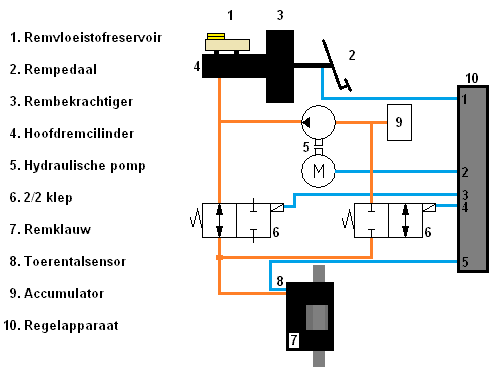
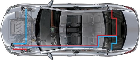
The illustration below shows an overview of the components of the ABS system.
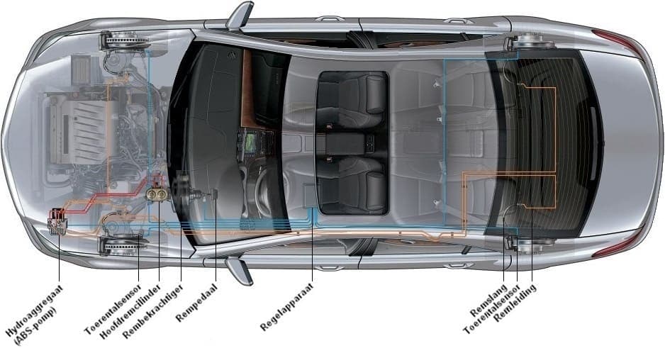
In the illustration above, two red lines are shown. These run from the master cylinder to the hydraulic unit. Hydraulic unit is another word for the ABS pump. The two red lines are related to the split brake system; left front with right rear and right front with left rear. If, for example, there is a leak at the left front wheel causing all brake fluid to leak away, it is still possible to brake with the other brake circuit. From the hydraulic unit, orange lines run to all wheels. In the hydraulic unit the braking force can be adjusted for each wheel individually.
A speed sensor is mounted at each wheel. This allows the speed of all four wheels to be continuously monitored. The blue lines are signal wires that are connected to the speed sensor. From each wheel, a signal wire runs to the control unit. The signals from the brake pedal and from the hydraulic unit also go to the control unit. In the car shown, it is located under the seat, in the interior of the car. Nowadays you increasingly see that the control unit is attached to the hydraulic unit. It is then one single assembly. If there is a fault in the system, for example due to a defective or contaminated sensor, a defective cable or a defect in the hydraulic unit, a warning light will illuminate in the instrument panel. The fault can then be read out with diagnostic equipment.
Speed sensors:
In the image below, the inductive speed sensor is visible in the installed position. This is a photo of a MacPherson strut from the front suspension. You can also see the toothed ring here, whose speed is measured by the sensor.
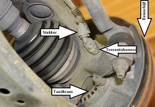
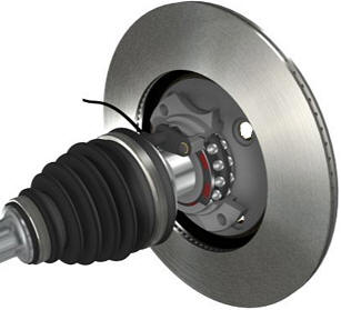
An ABS sensor can be designed as an inductive sensor (see image above), or as a magneto-resistive sensor (MRE sensor), in other words a Hall sensor (see image on the right). The operation of this sensor is described on the Hall sensor page. The latter sensor is used with the ABS magnetic ring that is integrated in the wheel bearing.
The signals from the inductive and Hall sensors can be measured with the oscilloscope. Examples of these measurements are shown and described below.
Inductive speed sensor:
The inductive speed sensor consists of a permanent magnet with a coil wound around it. The strength of the magnetic field changes when a tooth of the toothed ring (which is attached to the driveshaft) moves through the magnetic field of the permanent magnet. The change in the magnetic field causes a voltage to be induced in the coil. Each period in the speed signal corresponds to a tooth passing the sensor. The number of teeth on the ring and the rotational speed of the driveshaft determine the frequency and amplitude of the signal.
Hall sensor:
With the magneto-resistive sensor (MRE sensor), in other words the Hall sensor, a metal ring with magnets also moves past the sensor. The magnetic ring is located on the driveshaft or in the wheel bearing. The frequency of the square-wave voltage depends on the rotational speed and the number of teeth on the metal ring. The amplitude (the height of the signal) remains the same.
MRE sensors require a supply voltage to operate. Nevertheless, these sensors often only have two wires (and therefore two connections). The sensor sends the signal via the negative cable to the ABS control unit. The signal is formed because the electrical resistance of the semiconductor plates changes when they are exposed to an alternating magnetic field.
The signals from the speed sensors are passed on to the ABS control unit. The signals from the four wheels are compared with each other. When the vehicle is driving through a bend, the wheel speed on the inside of the bend will be lower than that of the wheels on the outside of the bend. This is measured, but naturally falls well within the margins.
When the wheel speeds differ too much from each other while braking, the ABS control unit will ensure that the hydraulic unit will reduce the brake pressure on the respective (braking too hard) wheel. If the difference in wheel speed is too great during acceleration, the engine power will be abruptly reduced by the engine management system.
In the event of faults in the ABS system, the signals can be measured with the oscilloscope. These can be measured at the wheel, but also at the control unit. By measuring at the wheel, it can be checked whether the ABS sensors are working properly. When measuring at the control unit, it can be ruled out whether defective wiring is the cause of the fault.
During the measurement it can be checked whether the frequency and amplitude of the inductive sensor are correct. With the Hall sensor it can be checked whether the frequency of the signal is correct while the wheel is turning. Rotate the wheel through full rotations so that any defects on the teeth can be quickly recognised. With damaged teeth, a deviation in the purity of the sensor signals will be visible (think of a frequency that is wider with each rotation than is intended).
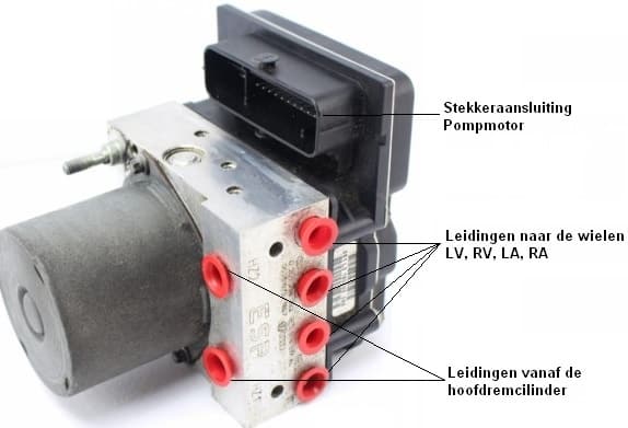
Hydraulic unit:
The bottom left image shows a hydraulic unit with an integrated control unit. This can be seen, among other things, from the large number of pins in the connector.
You can also see the connections for the lines from the master cylinder and to the wheels. The separate brake circuits (left front with right rear and right front with left rear) are integrated in this pump unit.
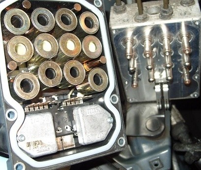
When we dismantle the hydraulic unit, the valve block becomes visible. The bottom right image shows the inside of the hydraulic unit.
Hydraulic circuit:
In the hydraulic diagram below, the components in and around the hydraulic unit are visible. To understand the operation, components and symbols, the page basic principles of hydraulics can be consulted.
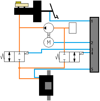
The diagram below is drawn for one wheel. Numbers 5, 6 and 9 are internal. Another wheel uses the same components, apart from the 2/2 valves (6), only with different connections. In other words, if the diagram of the complete car were to be drawn, there would be six more 2/2 valves next to it, each with their own lines. To keep it clear, only the diagram for one brake circuit is shown now.
Situation 1: When not braking and during steady braking:
The diagram on the right shows the situation when not braking and during steady braking. The brake pedal (2) is pressed, causing a fluid pressure from the master cylinder (4) to be applied to the left-hand 2/2 valve (6). This 2/2 valve has an open connection to the brake caliper (7). As the fluid pressure to the brake caliper increases, the brake pads will be pressed against the brake disc. Braking will then occur. The speed sensor (8) registers the number of revolutions made by the wheel.
Situation 2: ABS active, maintaining brake pressure:
This diagram shows the situation when braking hard and the wheel deceleration is too great. The ABS sensor at the brake has passed the speed signal to terminal 5 of the control unit, which is lower than that of the other wheels. The control unit reacts to this and closes the system towards the brake caliper.
This happens as follows: a certain current is applied to pin 3 of the control unit, energising the solenoid on the left-hand 2/2 valve. The valve is pushed to the left against the spring force. As a result, the supply of new brake fluid to the brake caliper is blocked. The right-hand 2/2 valve remains in the same position, so no brake fluid can flow to the brake or back. The pressure is thus kept constant. The control unit again checks whether the difference in wheel speed between the relevant wheel and the other wheels differs too much. If the difference in speed is minimal, or if there is no longer any speed difference because the brake pressure has been kept constant, the control unit removes the current from pin 3. The 2/2 valve springs back to its original position, making situation 1 applicable again. If the speed difference does not change, or even becomes greater, the brake pressure of the relevant wheel must be reduced. This happens in situation 3.
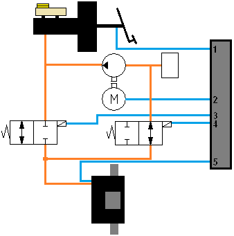
Situation 3: ABS active, reducing brake pressure:
To reduce the brake pressure, brake fluid must be pumped out of the line between the 2/2 valve and the brake caliper. This is shown in the diagram above.
Now pin 4 is also supplied with current, so that the right-hand 2/2 valve is energised. This is also now pushed into the left-hand position, opening the passage between the brake caliper and the hydraulic pump. At this point, the pump motor will start running and pump the brake fluid from the brake caliper to the master cylinder. The fluid is now pumped back to the reservoir against the force of the master cylinder. The pressure is reduced and the wheel will start to rotate again.
Summary:
While driving and braking lightly, situation 1 applies. During braking where the wheel is about to lock, situation 2 applies, and where the pressure needs to be reduced due to the locking wheel, situation 3 applies. During braking the situation will keep changing. If situation 3 applies, in which brake fluid is pumped away from the brake, the wheel will then need to be braked again. Otherwise the vehicle would not be able to brake forcefully enough. It then switches back to situation 1, then again to situation 2 and then again to situation 3. This continues until the driver stops braking, or until the vehicle is driving on a different surface that is, for example, rougher (a higher coefficient of friction).
ABS control cycle:
The control cycle of the ABS is shown in the graph below. Various factors have been added, such as the vehicle speed (A) with wheel speed, the tangential wheel acceleration (B), the activity of the system (C) and the brake pressure (D).
The graph is also divided into 9 time periods. In each period, a change is visible because the system is being controlled. The total time period is about 20 milliseconds and is divided into 9 unequal segments. The explanation of the lines is shown below the graph.
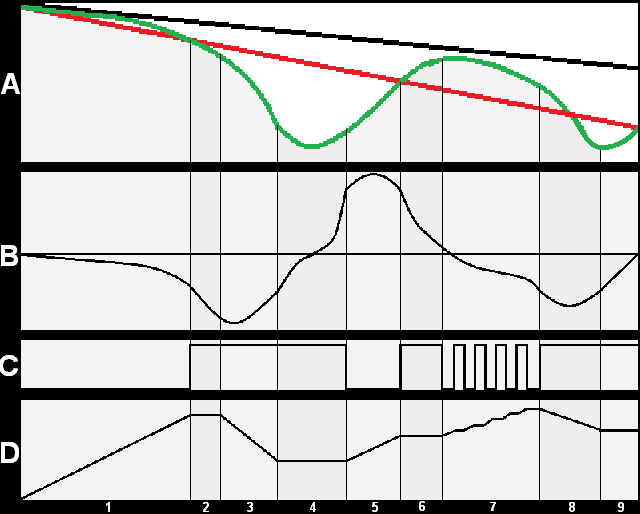
A: The black line is the vehicle speed, the green line the wheel speed and the red line the reference speed. The vehicle speed decreases (period 1), but the wheel speed decreases much faster. In doing so, the red reference line is crossed. At the moment when the green line ends up below the red line (from period 2 onwards), wheel slip can occur. The ABS will therefore intervene.
B: The line represents the tangential wheel acceleration. An example: by turning the wheel and braking gently, the line at B will remain close to the zero line. If you now turn the wheel at the same speed and brake harder, the line will deflect further downwards. The same happens when accelerating; by turning the wheel very quickly from 0 to 10 km/h, the line will shoot further upwards than if it takes you 5 seconds to turn the wheel from 0 to 10 km/h. In short, this is the tangential wheel acceleration.
C: This line indicates where the pressure in the system is stabilised; the ABS is then active. Where the line at C is low (on the zero line), the ABS system is not active. In period 7 the ABS is controlled in a pulsed manner, so that the wheel speed does not decrease too quickly.
D: This line represents the brake pressure. The brake pressure increases until the green line (A) of the wheel speed crosses the red reference line. The ABS is activated (C) and ensures that the tangential wheel acceleration does not become too low. The tangential wheel acceleration is at the zero line in period 4; exactly the moment at which the wheel speed in (A) goes from negative to positive. The pressure is kept constant at that moment. In period 7 the pulsed control is clearly visible. The brake pressure is now increased gently so that the wheel does not decelerate too quickly.
Control principles to prevent µ-split:
The ABS can be set individually for each wheel using this information. The wheel speed sensors register the speed of each wheel. This is necessary because in all situations the maximum achievable coefficient of friction must be weighed against the steerability of the vehicle. When the vehicle is driving with the left wheels on dry asphalt and the right wheels in the soft roadside and maximum braking force is applied, the vehicle will become unsteerable and rotate around its axis. The difference in braking force between the wheels on asphalt and on ice causes a yaw moment that leads to a change in course. This situation is called the µ-split situation. The µ is pronounced as “mu”. To prevent this scenario, several control principles are applied:
- The individual regulation (IR): here the brake pressure is set to the maximum coefficient of friction of each wheel. High yaw moments can occur, but the maximum braking forces are achieved.
- The select-low regulation (SL): the wheel with the lowest coefficient of friction determines the brake pressure for the other wheel. In this case, the maximum achievable braking force is not used, but the yaw moment is low.
- The select-high regulation (SH): the wheel with the highest coefficient of friction determines the brake pressure for the other wheel. The select-high regulation is only used for traction control (ASR) systems.
- The select-smart or modifying regulation: during braking, the system switches from select-low to individual regulation. This can achieve a compromise between yaw moments and maximum braking forces. This regulation is often used on commercial vehicles.
In most cases, the brake system of a passenger car is diagonally (crosswise) split. An example of this is shown in the image below. The red brake system is for left front and right rear and the blue brake system is for right front and left rear.
The front wheel brakes are controlled using the individual regulation (IR). The brake pressure of one front wheel is set to the maximum coefficient of friction of the other front wheel. During an emergency stop, the front wheels will individually seek the maximum achievable braking force.
The rear wheel brakes are controlled according to the select-low (SL) principle. The regulated brake pressure of the rear wheel with the lowest coefficient of friction determines the brake pressure of the other rear wheel. The braking torque of both rear wheels will remain the same.
Measurements of a vehicle with and without ABS:
To get a good picture of the influence of the ABS system on a vehicle, this section shows two graphs of measurements that demonstrate the difference of a decelerating vehicle without and with ABS.
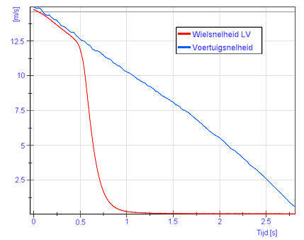
Vehicle speed versus wheel speed without ABS:
The graph on the right shows the vehicle speed relative to the wheel speed.
From t = 0 seconds, the vehicle speed is 15 metres per second. At that moment the brake pedal is pressed to the maximum. The vehicle speed decreases linearly to 0 m/s between
t = 2.75 and 3.00 seconds. The wheel speed drops completely to 0 m/s between t = 0.5 and 1.0 seconds. This means that the wheel already has a speed of 0 m/s, so it is stationary, while the vehicle is still moving. At that moment a wheel is locked. The wheel is skidding over the road surface while the vehicle has not yet come to a stop. In this situation the ABS is therefore not active.
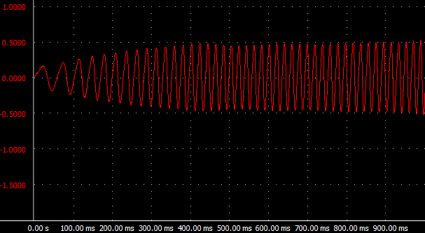
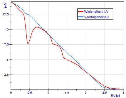
Vehicle speed relative to wheel speed with ABS:
In the graph on the right, the blue line behaves the same way; at a vehicle speed of 15 m/s, maximum braking is applied until 0 m/s. This again takes place within a time span of 3 seconds. Now that the ABS is active, the red line at t = 0.3 seconds does not drop to 0 m/s, but the speed of the wheel increases again. This can be seen from the red line, which first goes downward and then rises again shortly before t = 0.5 seconds. The brake pressure is reduced by the ABS at a speed of 7.5 m/s. The speed of the other wheels is equal to the vehicle speed and therefore to the blue line. The ABS sensor of the left front wheel registers the deceleration. The ABS computer recognises the difference in speed and intervenes. The brake pressure is reduced by the hydraulic unit until the blue and red lines are equal again. At that moment, the brake pressure is kept constant. Until the vehicle comes to a standstill, the ABS continues to regulate the speed of the slipping wheel.
The pressure in the master brake cylinder relative to the wheel brake cylinder without ABS:
The force applied to the brake pedal is converted into brake pressure in the master brake cylinder by means of fluid displacement. This brake pressure is shown in the graph below by the blue line.
Regardless of whether the wheel is slipping or not, the brake pressure in the wheel brake cylinder (the red line) remains equal to the pressure in the master brake cylinder. This is therefore the situation without ABS.
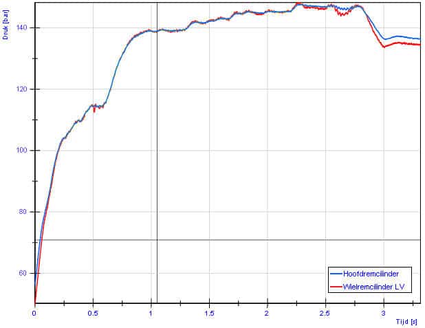
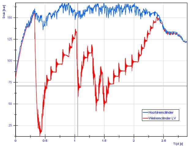
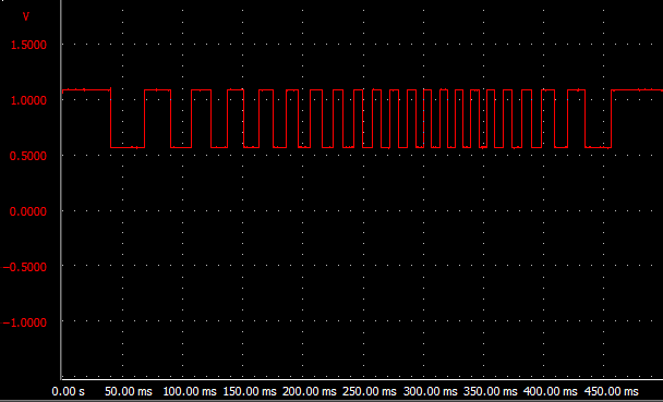
The pressure in the master brake cylinder relative to the wheel brake cylinder with ABS:
In the situation where the ABS is activated, the pressures in the master brake cylinder and in the wheel brake cylinder are no longer equal. The pressure in the master brake cylinder remains high because the driver keeps the brake pedal depressed. In the graph, the red line drops at t = 0.3 seconds; here the ABS reduces the brake pressure. The reduction of the brake pressure ensures that the wheel starts rolling again. From t = 0.4 seconds, the brake pressure is then increased step by step until the speed of the wheel is equal to that of the other wheels. This is the case at t = 2.35 seconds.