Introduction:
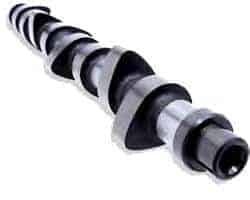
The camshaft is an important part of the engine. The camshaft ensures that the valves are opened and closed so that air can flow in and out of the cylinder. The camshaft rotates so that the cam opens the valve against the spring force of the valve spring. The valve spring ensures that the opened valve closes when the cam continues to rotate.
The camshaft is located at the top or bottom of the cylinder head, or in the bottom of the engine block. The camshaft is driven by the timing belt, chain or gears. See more about this in the chapter timing drive.
Overhead camshaft:
Nowadays only overhead camshafts are used. The camshaft is then located in the cylinder head. The advantage of engines with an overhead camshaft is that they can handle higher speeds than engines with a camshaft located below.
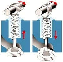
In the left image you can see that the valve is closed because the valve spring presses the valve shut and that the camshaft rotates clockwise. In the right image the camshaft has rotated, causing the cam to push the valve down. The spring is now compressed, so the valve is pushed down. At the moment the camshaft has rotated further, the valve spring will push the valve back up again. The valve spring exerts a counterforce of approximately 20 kg.
The valves of a four-stroke engine are opened by 1 or 2 camshafts. In the version with 1 camshaft it operates both the intake and the exhaust valves.
In the version with 2 camshafts, one camshaft operates the intake valve(s), and the other the exhaust valve(s). The 2 camshafts can be driven one after the other by the same timing belt, but there are also systems where one camshaft drives the other by means of a separate belt or chain (see the images below)
The images below are just examples of the construction with the timing belt. The principle is the same with a timing chain.
The top left image is of an engine with a single camshaft. It operates both the intake and the exhaust valves. This is usually used for, for example, four-cylinder engines with 8 or 12 valves (so with 2 or 3 valves per cylinder).
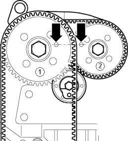
The middle image is of an engine with a double camshaft, which is driven by two timing belts. Camshaft gear (1) is driven directly by the crankshaft with the large belt. On the back of the pulley of gear 1 there is a small gear over which the rear belt runs. This rear (small) belt drives camshaft gear (2). The small belt requires a separate tensioner pulley. This is usually used for four-cylinder engines with 16 or more valves (so 4 or more valves per cylinder).
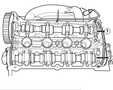
The right-hand image is of an engine with two camshafts. The camshafts are driven by both a belt and a chain. Camshaft 1 is driven by the timing belt, which in turn is driven by the crankshaft. Camshaft 2 is driven by the chain which is driven by camshaft 1. This chain, with a tensioner or adjustment mechanism, is mounted under the valve cover. This is usually used for e.g. four-cylinder engines with 16 or more valves (four or more valves per cylinder).
Underlying camshaft:
In the past, engines were built with an underlying camshaft. Nowadays, passenger car engines are only built with overhead camshafts. The construction with the underlying camshaft is disappearing. The disadvantage of this design is that these engines can handle lower maximum speeds, because there is a lot of mass between the camshaft and the valve. At high speeds, excessive play will occur and the valve will no longer open and close at the correct times.
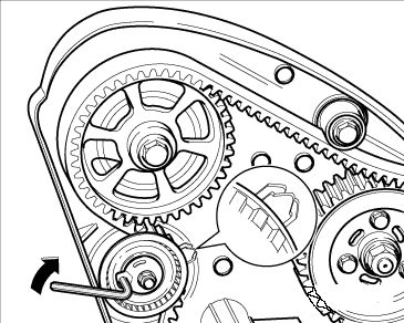
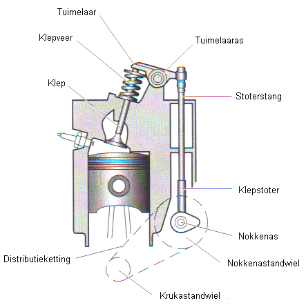
The crankshaft drives the underlying camshaft by means of a small timing chain or belt (see image below). The camshaft pushes the tappet and the pushrod straight up. The right-hand side of the rocker arm is pushed up. The rocker arm “rocks” around the rocker arm shaft, causing the left side to be pushed down. As a result, the valve is pushed down against the force of the valve spring. When the camshaft has rotated further, the valve spring closes the valve and the rocker arm returns to its initial position.
High-performance camshafts:
When the cam is more oval and longer, the valve will remain open longer. More air can then flow into the cylinder. This results in a power gain.
This principle is used, among other things, in engine tuning. This is referred to as ‘high-performance camshafts’. When the tip is sharper (more pointed), the valve will close faster again. It must also be slightly convex, because otherwise the valve would slam back onto the seat at too high a speed, causing heavy wear on the valve seats. When designing an engine, this is also carefully tested, so that camshafts are installed that are optimally suited for power, fuel consumption and emission values.
Valve overlap:
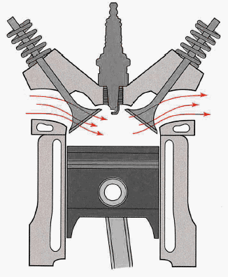
During valve overlap, the intake and exhaust valves are briefly open at the same time. At the end of the exhaust stroke, when the piston is almost at TDC, the intake valve opens before the exhaust valve is closed. In this situation the speed of the exhaust gases leaving the combustion chamber is so high that intake air is already drawn in by the vacuum effect. After the exhaust valve has closed and the piston moves to BDC, the intake valve opens fully. The intake air will then fill the combustion chamber.
The advantage of valve overlap is that the speed of the incoming air is increased when the intake valve opens, resulting in a higher volumetric efficiency.
The image shows the situation in which the intake valve (left) and the exhaust valve (right) are open at the same time.
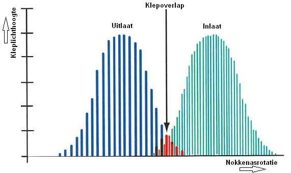
The diagram shows the opening and closing of the exhaust and intake valves. Because the camshaft rotates, the exhaust valve is opened and closed again (the blue lines). In the middle of the graph the valve overlap takes place. This is shown in red. The intake valve (shown with green lines) is already opened a bit here.
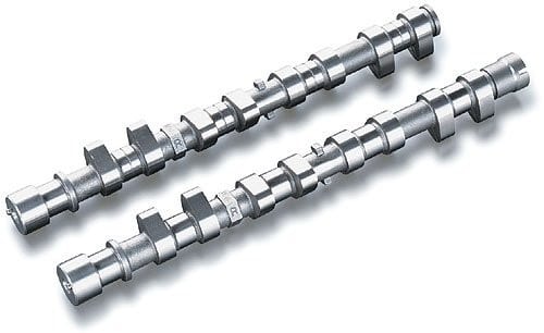
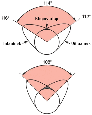
Valve overlap is obtained by the cam profile. In the image below you can see that on the upper camshaft the highest cam lobes are 114 degrees apart. In the middle of the image, valve overlap occurs because the end of the intake cam and the beginning of the exhaust cam are higher than the round section of the camshaft. This is the part where the intake and exhaust valves are open at the same time.
The closer the cam lobes are placed to each other, the more overlap occurs. This can be seen from the difference between the upper and the lower camshaft, where the cam lobes on the lower camshaft are 108 degrees apart.
Valve overlap therefore always occurs and cannot be changed due to the fixed cam profile on the camshaft. The amount of valve overlap is determined by the engine designer.
Variable valve timing and valve lift:
The power of the engine largely depends on the camshaft. If it has cams that are long and oval, the valves remain open longer. More air can therefore flow in and out of the engine, which results in more power. If the cams are shorter and pointier, the valve will open less far and close earlier, allowing less air to flow in and out, so it also produces less power. The advantage is that fuel consumption can be reduced.
Low engine speeds with low load require:
- Intake valves to open late and close early.
- Exhaust valves to open late and close early.
High engine speeds with high loads require:
- Intake valves to open early and close late.
- Exhaust valves to open early and close late.
Car manufacturers always look for a compromise. Variable valve timing adjusts the camshaft to the required position at the engine speed at which the engine is running. Variable valve lift is also a technique used to gain various advantages by changing the distance by which the valve opens.
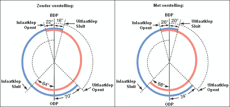
With variable valve timing, the camshaft rotates relative to the adjustable camshaft gear (see image). With this system it can be controlled whether the valves open earlier or later, but it cannot be arranged that the valves remain open longer. If the valve opens earlier, it will also close earlier, because the shape of the camshaft remains the same. More explanation is given on the page variable valve timing.
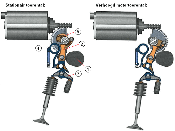
Variable valve lift is a technique that ensures that the lift of the valve is adjustable. This controls how far the valve opens. That is beneficial for both fuel consumption and engine power. The image below is an example of this. This is BMW’s Valvetronic system.
Variable valve lift is only used on the intake camshaft. There are several techniques that are used by different manufacturers. On the page variable valve lift the different techniques are described in detail.
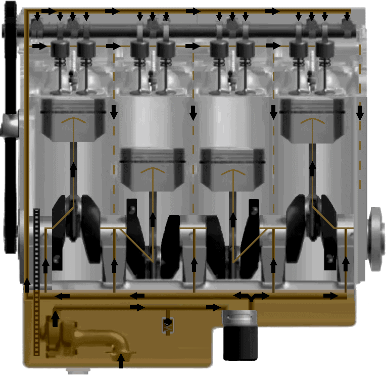
Lubrication:
The camshaft must be lubricated, just like all other moving components in the engine. Through pipes with holes or jets, the camshaft is supplied with oil in the right places. The operation of the entire lubrication system is described on the page lubrication system.