Introduction:
In this case study we deal with a real fault that can be encountered in practice. To be able to trace faults, one must have the knowledge and skills to operate diagnostic equipment, consult wiring diagrams, take measurements with test equipment and assess measurement results. Therefore, first study the following pages:
- OBD diagnostics;
- Reading wiring diagrams;
- Sensor types and signals (passive, active and intelligent);
- Troubleshooting sensor wiring;
- Measuring with the multimeter and oscilloscope.
Reading the fault memory:
In this case study we deal with a car with loss of power. The engine warning light is on.
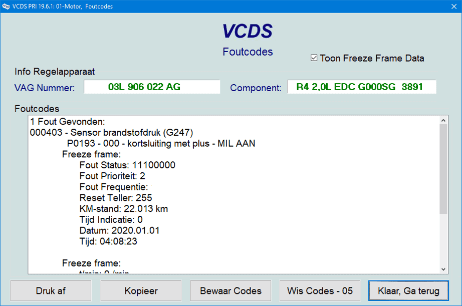
In the event of a customer complaint and/or warning lights being on, we first read out the car. The following fault is active:
P0193 – fuel pressure sensor G247 – short circuit to positive.
The fault returns immediately after clearing. So it is permanently present.
Looking up the wiring diagram:
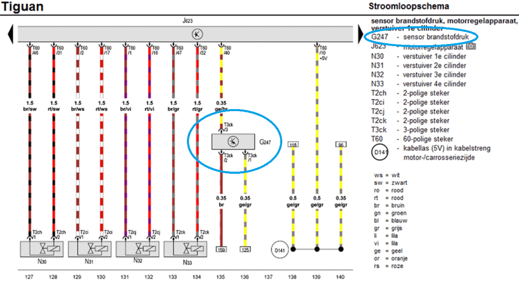
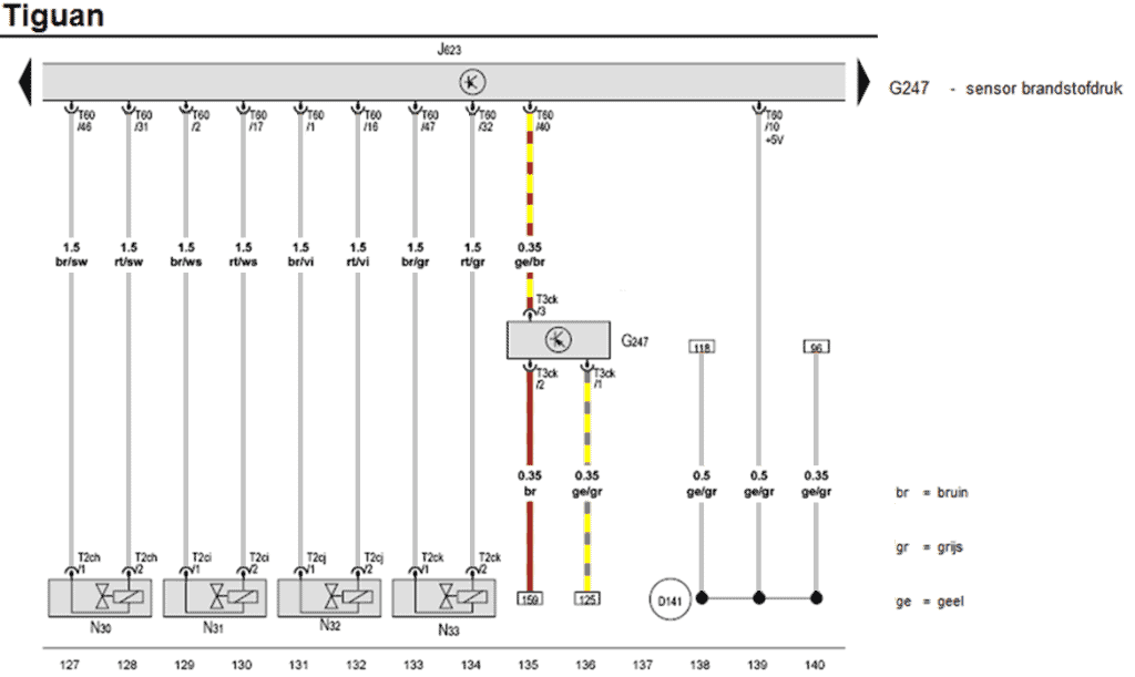
We look up the fuel pressure sensor with component code G247 in the wiring diagram. There is a three-pin connector (T3ck) on the sensor. The yellow/brown wire (pin 3 of the sensor) is connected to pin 40 on the engine ECU (J623). This is the signal wire. The other two wires (pins 1 and 2) go via references 159 and 125 to other coordinates in the diagram.
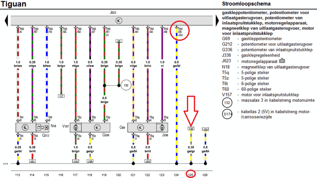
We look up coordinate 125 to trace the yellow/grey wire. In the next diagram we see that the yellow/grey wire is connected to junction D174 (5-volt supply rail) which is connected to several components. The supply rail reaches the ECU via the yellow/blue wire at pin 25. This is the supply wire for, among others, the fuel pressure sensor.
We go back to the diagram of the fuel pressure sensor. We know that pin 1 is connected to the common positive supply for the sensors.
We now follow reference 159 and arrive in the next diagram. The brown wire ends on a ground rail and is connected to pin 53 of the ECU.
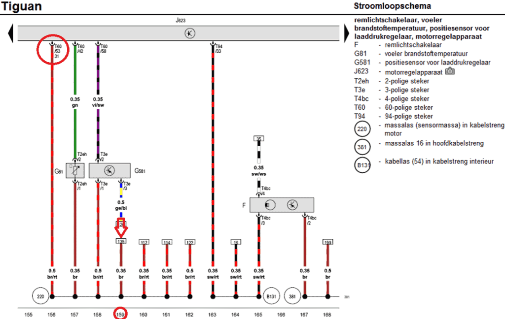
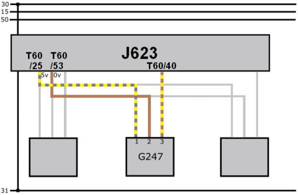
We return to the original diagram and focus on the fuel pressure sensor. We grey out the wires we are not using.
The original wiring diagram contains references, which can lead to confusion. For that reason we create a simplified diagram. This shows the common supply and ground (pins 25 and 53) and the signal wire (40).
Measuring with the multimeter:
With the voltmeter we measure the supply voltage relative to ground. The multimeter shows 5.00 volts on the display: from this we know that both the positive and ground wires are in order.
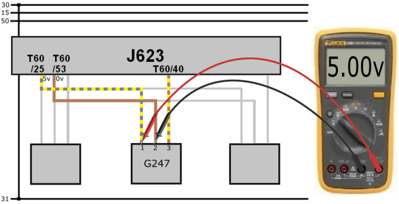
The signal voltage (measured relative to ground) is 2.9 volts. This value is realistic: based on this voltage we cannot conclude that there is a short circuit to positive.
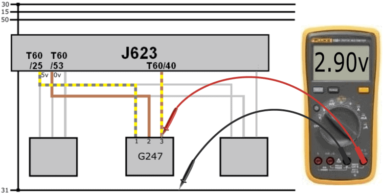
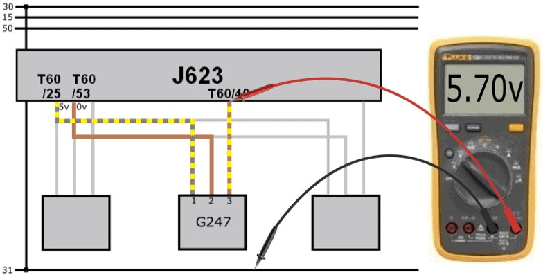
The signal voltage of 2.9 volts from the sensor is sent to the ECU. Yet at the ECU we measure a voltage of 5.7 volts.
The voltage at the ECU side is higher than the voltage supplied by the sensor.
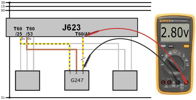
With a voltage difference across a wire there may be a contact resistance. However, the voltage at the sensor side should then be higher; in this case the voltage at the “receiving” end is higher.
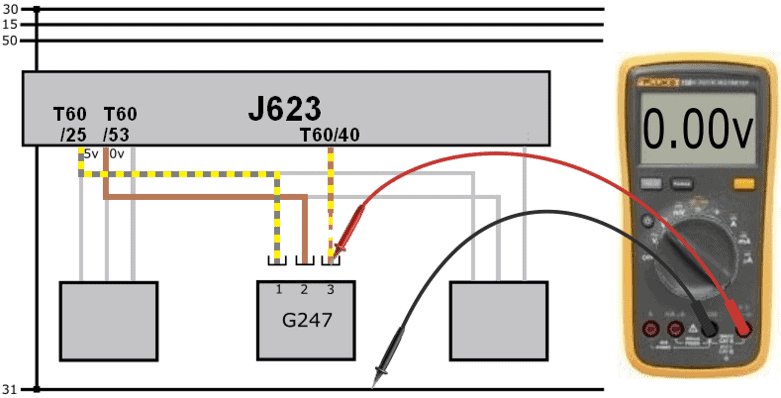
The connector is removed from the sensor. When measuring in the connector we measure 0 volts.
The voltage difference of 2.8 volts can be explained:
- At pin 40 of the ECU we measure a voltage of 5.7 volts due to the internal circuit;
- The sensor sends a voltage of 2.9 volts;
- The voltage difference between the sensor and ECU is therefore: (5.7 – 2.9) 2.8 volts.
- With the connector removed we measure 0 volts in the connector, but still 5.7 volts at the ECU side.
- Conclusion: the signal wire is interrupted.
The wire break was located in a section of the wiring loom that was not attached to a fixed point. During an earlier disassembly the wiring loom bracket had broken off. The loom had been able to move for quite some time. Eventually the signal wire chafed through. After repairing the signal wire and some other slightly damaged wires, the wiring loom bracket was correctly refitted and the fault did not return after clearing.
Why we measure a voltage of 5.7 volts:
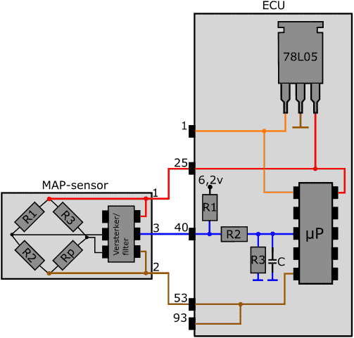
In the next image the circuit in the ECU is shown. The signal from the active MAP sensor is sent via the blue wire to pin 40 of the ECU. In the ECU there are a number of resistors (R1, R2, R3) and a capacitor (C). The signal wire from the sensor is connected inside the ECU between resistors R1 and R2.
The sensor cannot send information to the ECU in the following situations:
- the connector of the sensor has been disconnected;
- the positive, ground or signal wire is interrupted;
- the sensor is defective (internal interruption).
In these situations no current flows from the sensor to the ECU. However, there is an active current circuit inside the ECU: current flows through R1, R2 and R3.
We are dealing here with a voltage divider: three resistors are connected in series. The microprocessor measures the voltage between R2 and R3. The supply voltage to the first resistor is 6.2 volts. Each of the three resistors takes up part of this voltage. After the last resistor we see a ground symbol. At that point the voltage is (of course) 0 volts.
With an interrupted signal wire, the first resistor takes up a voltage of 500 mV. Between resistors R1 and R2 we therefore measure a voltage of: (6.2 – 0.5) = 5.7 volts. In the case where the sensor does not provide any information, we therefore measure a voltage of 5.7 volts at pin 40 of the ECU.
Thanks to ACtronics for providing the information about the circuit in the ECU.