Potentiometer:
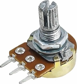
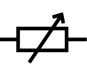
A potentiometer, also called a potmeter or angle rotation sensor, is often used in automotive engineering as a position sensor for, for example, the accelerator pedal, the throttle valve, or the fuel tank level. The wiper (sliding contact) moves via an adjustable part over the carbon track, which results in a change in resistance and thus allows the position to be determined. The three images below show a real potmeter, the components inside a potmeter, and the symbol of a potmeter.
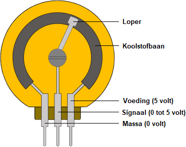
The resistance of the signal terminal changes when the wiper is rotated to another position on the carbon track. However, a control unit cannot “read” resistance. A control unit switches a reference voltage of 5 volts and a ground to the two outer terminals of the potentiometer. Because current now flows through the carbon track, the 5-volt voltage is consumed in the carbon track. At the input there is a voltage of 5 volts and at the output 0 volts. Halfway along the carbon track, half of the voltage has been used: at this point the voltage is therefore also half of the reference voltage, namely 2.5 volts. The voltage that is sent via the wiper and the signal terminal to the control unit provides the control unit with sufficient information to determine the position accurate to the degree. This is used, among other things, for the accelerator pedal and throttle position sensors.
The 5-volt supply is a commonly used value, because the on-board voltage remains above 5 volts under all operating conditions. If important sensors were to operate at a voltage of 12 volts, they could malfunction while starting the engine: during cranking in winter with a weak battery, the starting voltage can drop to 10 volts.
Another possibility is that the potentiometer provides a voltage for an electrical circuit with, for example, an op-amp, as with the headlamp adjustment. In that case, the potentiometer operates with a voltage of 12 to 14 volts.
The potentiometer can often travel through an angle of 270 degrees. Here we assume a potmeter with a linear characteristic. The animation shows the output voltage at seven different positions of the wiper:
- 0 degrees: 0 volts
- 45 degrees: 0.8 volts
- 90 degrees: 1.7 volts
- 135 degrees: 2.5 volts
- 180 degrees: 3.3 volts
- 225 degrees: 4.2 volts
- 270 degrees: 5 volts
In practice, the output voltage changes with each degree of rotation of the wiper over the carbon track:
- The total travel is 270 degrees;
- The resistance is 10 kΩ (10,000 Ω)
- With each degree of rotation, the resistance changes by 37 Ω
- The voltage changes with each degree of rotation by 18.5 mV (0.0185 V).
In the animation above we see that at 0% rotation the signal voltage is 0 volts and at 100% it is 5 volts. However, this can also be the other way round: 0% rotation 5 volts and 100% 0 volts.
Resistance characteristic:
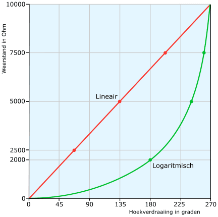
With a linear potmeter, each degree of angular rotation corresponds to a fixed value. For example, a 270 Ω potmeter that can travel through 270° gives a resistance difference of 1 Ω per degree of rotation. With a logarithmic potmeter, the change in resistance does not increase linearly but progressively.
In the following image we see the linear characteristic (red) of the potmeter from the previous paragraph. In addition, the logarithmic characteristic (green) of the other type of potmeter can also be seen. Logarithmic potmeters are mainly used to simulate physical processes.
The signal voltage of these potentiometers varies in proportion to the resistance.
Signal voltage:
The potentiometer is connected as follows:
- Supply voltage of 5 volts from the control unit;
- Ground of 0 volts via the control unit;
- The wiper passes the analogue voltage from 0 to 5 volts to the signal terminal of the control unit.
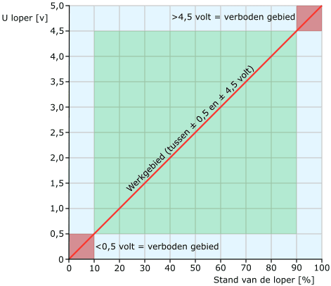
The operating range of the potentiometer lies between 0.5 and 4.5 volts. Manufacturers may also choose other extreme values, for example: 0.4 to 4.6 volts. The signal from the potentiometer must never fall outside this operating range. If the control unit detects that the signal voltage enters the forbidden area, this is recognised as faulty and it stores a fault code.
- Signal voltage 5 volts: indicates an open ground wire or a short to positive;
- Signal voltage 0 volts: indicates an open supply wire or a short to ground.
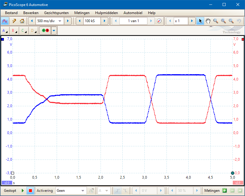
To guarantee the reliability of the signal, a dual potentiometer is used for an accelerator pedal or a throttle valve. The signals can be mirrored vertically with respect to each other (as in the image), or proportional at a different voltage level. In any case, they must not be identical. The ECU compares the signal voltages.
When the ECU detects an implausible signal on one of the two potentiometers (spikes, or the signal entering the forbidden area) it switches to so-called limp-home mode and uses the second signal.
On the page: accelerator pedal and throttle valve the application of the potentiometer is discussed in detail, including “throttle by wire” and oscilloscope traces of faulty signals.
See also: sensor types and signals.
Voltage divider:
A series circuit consisting of resistors acts as a voltage divider. The supply voltage is distributed over the resistors in this series circuit or voltage divider. The smallest resistance has the smallest voltage drop and the largest resistance has the largest voltage drop.
The images below show the potentiometer in a real situation and in a schematic representation, connected to a 12-volt power supply. The wiper of the potentiometer is in the middle position. In the middle image we see the potentiometer in schematic form. On the right we see the voltage divider with two separate resistors with terminal 3 in between. The three schematics are equivalent to each other.
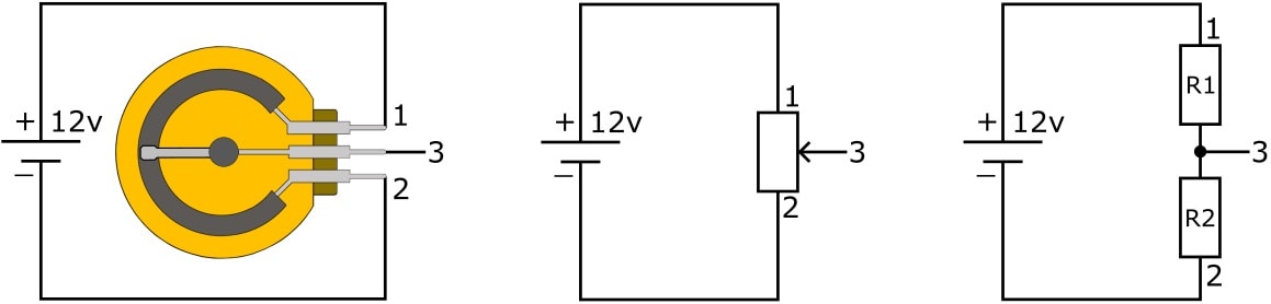
Because the potentiometer has a fixed resistance value, the sum of the resistances (R1 + R2) is equal to the total resistance. Moving the wiper causes a change in resistance of R1 and R2 (right-hand schematic). The output voltage on pin 3 is high when the wiper is at the top and the resistance value R1 is small.
Potentiometer for mirror adjustment:
Two electric motors provide horizontal and vertical adjustment of the mirror glass. In modern vehicles, the control is carried out via a control unit. In the diagram below we see this control unit (J386). The control unit actuates the adjustment motor as soon as:
- the driver operates the mirror adjustment switch, or:
- reverse gear is selected and a mirror glass needs to be tilted downwards (usually the one on the passenger side);
- the memory function has to set it to another desired position. This is usually identified based on the key (remote control);
- the technician actuates the adjustment motor via an actuator test using a diagnostic tool.
In order to move the mirror glass to the desired position, it is necessary to determine the position of the mirror glass. Potentiometers G791 and G792 send the signal via the grey/yellow and blue/red wires to the control unit. At the moment that the mirror positions of two different drivers are stored under their own key number, the adjustment motor moves to the correct position as soon as the respective driver unlocks the doors with the remote control. In addition to the correct mirror glass positions, the electric steering column adjustment and seat position adjustment (if present) are usually also set to the stored positions. On the page: exterior mirrors and mirror adjustment, the control methods of the mirror adjustment motors are described.
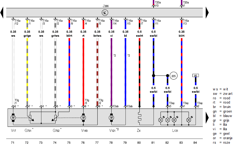
Legend:
- J386: door control unit;
- V17: motor for horizontal mirror glass adjustment;
- G791: potentiometer for horizontal mirror glass adjustment;
- G792: potentiometer for vertical mirror glass adjustment;
- V149: motor for vertical mirror adjustment;
- V121: motor for power-folding mirror function;
- Z4: mirror heating element;
- L131: indicator lamps in exterior mirror housing.
In the above wiring diagram, electric motor V121 (power-folding mirror function) can also be seen. Because no intermediate positions are required for the folding function, feedback from a position sensor is not necessary. After all, the mirrors are either folded out or folded in. When the end position is reached, the current draw of the electric motor increases, causing the ECU to “recognise” that the end position has been reached and thus to stop the actuation.
Potentiometers for the throttle actuator motor:
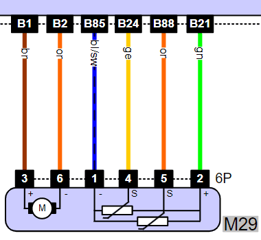
On this page, the potentiometer of the throttle actuator motor has already been used several times as an example. The following diagram shows the actuator motor (left) and the two potentiometers with common supply and ground and two signal connections (right). The signal connections (pins 4 and 5 in the potentiometer connector) provide signals with a difference in voltage progression:
- the progression is linear at a different voltage level, where the voltages rise and fall simultaneously, or;
- the signal voltages are opposite to each other.
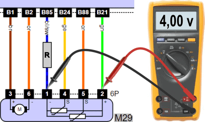
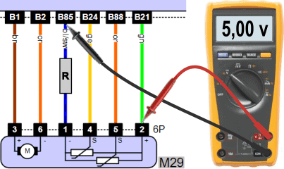
In the three images below, three measurements of the throttle position sensors and their common supply and ground can be seen. The supply voltage is again 5 volts and the signal voltages are within tolerance.

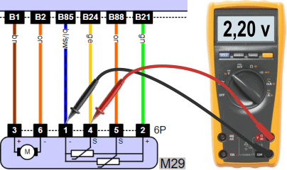
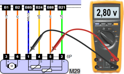
In the event of a fault, the level of the signal voltage may deviate. Two situations are possible:
- One of the signal wires contains a fault. Because the ECU compares the two signal voltages with each other, it recognises this incorrect signal and goes into limp mode. This is accompanied by the engine management warning light coming on and possibly reduced engine power;
- The supply or ground wire contains a contact resistance: in this case there is a voltage drop across the respective wire, causing both potentiometers to output a signal that is too low. Because the signal voltages are compared with each other and they do not deviate from each other, this is not recognised by the ECU. The signal voltages that are too low are accepted by the ECU and result in incorrect control of the throttle. The ECU continues to drive the throttle actuator motor until the desired position is reached. This can lead to subsequent faults in sensors and actuators related to the air supply due to a mixture that is too lean (positive fuel trim), faults in the lambda circuit, faults relating to the MAP sensor or the EGR.
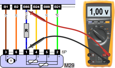
The fault in the situation above can be remedied by replacing the ground wire between pin B85 of the connector on the ECU and pin 1 of the connector on the throttle body.