Introduction:
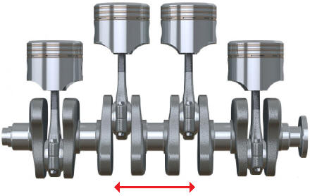
The working forces of the pistons are transmitted to the crankshaft via the connecting rod. The crankshaft is a solid shaft that converts the translational movements of the connecting rod into rotational movements. A crankshaft is a long shaft with one or more protruding crank throws. The connecting rods are mounted on these crank throws and are in turn connected to the pistons. When the piston moves from TDC to BDC (from top to bottom), the connecting rod is pushed downwards, which then causes the crankshaft to rotate.
At the front of the crankshaft are often the timing drive and the crankshaft pulley, possibly together with the torsional damper. At the rear are the flywheel and the clutch. At both ends there are crankshaft oil seals that provide sealing between the rotating crankshaft and the engine block.
A crankshaft is an important component in everything that produces motorised movement. The crankshaft must be designed to micrometre precision because it is subjected to large forces. Moreover, a crankshaft rotates at very high speeds, so even a small design or assembly error can lead to major imbalance and damage.
The engine speed, which is displayed for example by the rev counter in the instrument panel, is determined by the number of revolutions the crankshaft makes per minute. The crankshaft speed is measured by the crankshaft position sensor (also sometimes called the TDC sensor).
Crankpins:
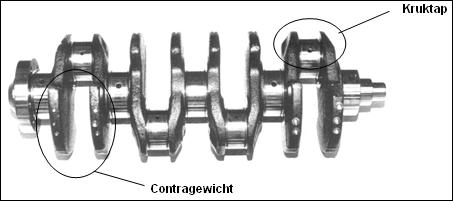
To distribute the combustion forces over the entire crankshaft, the power strokes are spread out. For this purpose, the crankshaft is fitted with crankpins. In a four-cylinder in-line engine these crankpins are offset by 180° relative to each other. In a V6 engine the crankpins are often offset by 60° relative to each other.
Counterweights & bearings:
The crankshaft is also subjected to mass forces resulting from the reciprocating mass movement. To compensate for these mass forces, counterweights are used that serve to counterbalance them. In certain engine designs, limiting the vibrations by means of the counterweights is not sufficient. In such cases, balance shafts are used in the engine. See the chapter on the balance shaft.
The crankshaft is mounted in the engine block by means of main bearings. The crankshaft in the image above has 5 main bearings, but there are also crankshafts that are supported by 3 bearings. Through drillings in the main bearings and crankshaft, the connecting rods and pistons are supplied with lubrication.
The crankshaft is also fitted with thrust bearings at one of the main bearings (flywheel side or the centre one). These bearings are intended to absorb the axial forces (in longitudinal direction) on the crankshaft resulting from depressing the clutch, accelerating and braking.
Oil pump:
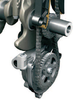
The oil pump is driven directly by the crankshaft. The drive can be via gears, but also via a chain (see image). Click here for more information about the oil pump.
Related page:
- Measuring radial and axial crankshaft play (mechanical diagnosis)