Introduction to OBD:
OBD is an abbreviation for On Board Diagnostics. OBD has both a control and a diagnostic function, especially in the ECU’s engine management system. A fault can be traced via the OBD system by reading it out with a diagnostic tester. The fault code can be looked up in the OBD Fault Code List (if the code is not make-specific).
TIP: Also visit the website GerritSpeek.nl, where you can find a lot of in-depth information about the possibilities of the VCDS program and detailed information about fault codes.
OBD 1:
This is the first OBD system, developed by GM (General Motors). It was introduced in 1980 and first used in the USA in 1988. The main purpose of this system was to limit emission values. The system was designed to detect its own defects and deviations, thereby limiting harmful emissions. When a defect or deviation was recognized, the MIL (Malfunction Indicator Lamp) would light up immediately and had to be read out by an automotive technician. The driver of the car was warned of the fault by the MIL and had to have the problem fixed as soon as possible.
All vehicles produced from 1991 onwards had to be equipped with OBD1. The first versions from Opel and Volvo, among others, used a flash code. Other manufacturers developed their own connector with their own fault codes. There were no guidelines for OBD 1, which is the case from OBD II onwards.
Flash code:
With the first generation of OBD1, the mechanic has to read out the flash code in order to determine the fault code. Often an action must be performed to make it start flashing; this action consists of:
- clicking two separate connectors together in the engine compartment or the interior;
- bridging two terminals in a connector, again in the engine compartment or in the interior.
A flash code consists of two or three digits. In the following image the check lamp flashes: 4x flash – short pause – 5x flash – long pause. This gives fault code 45, which stands for: lambda sensor – rich mixture detected.
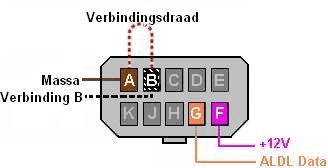
Opel:
This type of diagnostic connector is usually installed in the engine compartment. Bridging two terminals in this connector will cause the check lamp in the instrument cluster to start flashing.
- Bridge A-B: codes for the engine management system;
- A-C: automatic transmission;
- A-H: alarm system;
- A-K: ABS
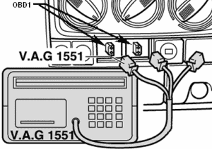
Volkswagen:
On Volkswagen vehicles there are 2 separate connectors for OBD1. The tester (in this case the VAG 1551) can be connected to these 2 connectors. By selecting the correct channel on the tester (01 for engine electronics), the fault memory could be read out and cleared in the service menu.
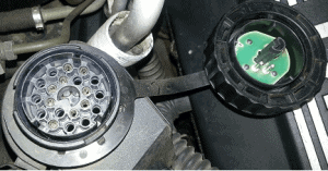
BMW:
On BMW vehicles, the OBD1 connector is round. This connector is connected to the diagnostic equipment by means of a cable. The faults are shown with descriptions on the display of the diagnostic tester. The faults can also be cleared.
OBD II and EOBD:
OBD II was introduced in 1996. From 2004 onwards, OBD became mandatory in Europe. In America it continues to be called OBD II and the European variant is called EOBD. They are almost identical, with just a few small differences; with EOBD it is not mandatory to perform EVAP monitoring (leakage of harmful fuel vapors), whereas this is mandatory in America. Cars from 2008 onwards must have OBD II and EOBD with CAN bus communication. Click here for more information about the CAN bus.
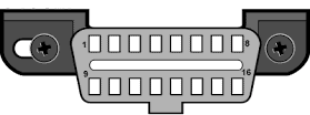
Various aspects were laid down (standardized); such as the type and location of the 16-pin OBD connector (Data Link Connector, abbreviated as DLC), the fault code structure and the communication protocols. The emission-related fault codes must be readable by everyone.
EOBD is mandatory for the drivetrain of all vehicles and is separate from the make-specific diagnostics. The EOBD constantly monitors all systems (such as the lambda sensor) via the engine management system and detects when the actual emission is one and a half times the emission of the type approval. The MIL will not light up immediately, but the system will store the fault. When a second trip is made under the same conditions and the emissions are again one and a half times higher than the maximum allowed, the MIL will light up. The driver is then alerted that there is a fault in the engine management system.
When the car is read out, a fault code appears on the scan tool. In technical terms, this code is also called a DTC (Diagnostic Trouble Code). This DTC can, for example, be a P-code. This code has a meaning; Click here to go to the OBD fault code list.
Reading out and clearing the fault memory:
The car can be read out with the help of diagnostic equipment. This must be connected to the OBD2 connector in the interior of the vehicle. The diagnostic tool then establishes a connection with, among other things, the gateway. This OBD2 connector is usually located near the driver’s seat, usually under the dashboard or in the center console.
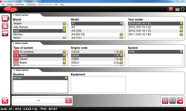
A special OBD2 cable must be connected to this connector. This cable must be connected to a scan tool. After the laptop has been connected to the interface and the cable, the diagnostic software can be started. First, some vehicle data must be entered, as shown in the image below:
After the connection is established, you are asked what you want to do next. One of the options is reading out a fault code. A fault code is also called a Diagnostic Trouble Code (DTC). A DTC consists of a letter followed by four digits.
- The letter P stands for Powertrain; this includes, among other things, the engine and the gearbox.
- The B stands for Body; this includes, among other things, the airbags, seat belts, heating and lighting.
- The C stands for Chassis; this includes, among other things, the ABS and ESP systems.
- The U stands for Network; this relates to, among other things, CAN bus communication.
The four digits indicate what the code is about. Extensive lists with codes and their meanings can be found on the internet.
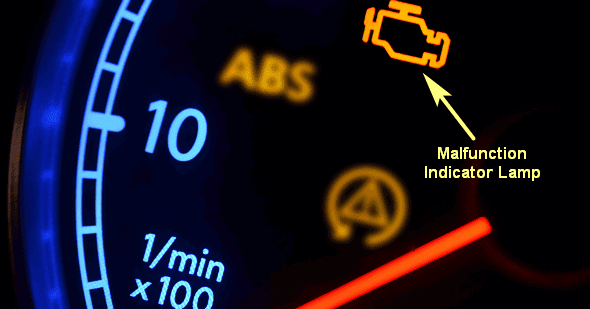
As an example, we take a car that runs irregularly at idle. The engine management lamp is on.
This lamp is also called the Malfunction Indication Lamp (abbreviated as MIL). When this lamp is on or has been on, you can be sure that a fault has been stored in the fault memory. It is then time to read out the car.
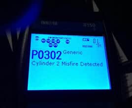
On the tester screen in the image, the fault code P0302 appears. This code indicates that a misfire has been detected on cylinder 2. This may have been present only once, may have occurred several times, or may be present permanently. Fault code P0301 occurs when a misfire is detected on cylinder 1, and fault code P0303 for cylinder 3, etc.
When a sensor sends a value that is outside the tolerances, the ECU checks which fault code belongs to it and stores this in memory. The diagnostic equipment also shows text; the software recognizes the code (e.g. P0302) and links text to it (Cylinder 2 Misfire Detected). All of this is pre-programmed in the diagnostic software.
Each manufacturer also has make-specific codes; for this reason, it is often necessary at the start to select the make, model, year of manufacture, engine code and fuel system. If the wrong make is selected, the wrong text may be linked to the fault code. Make-specific testers or very advanced test equipment also have diagnostic procedures integrated into the software. When a fault code is clicked, a test routine will be opened that can be followed step by step. At the end of the test, the software will draw a conclusion or indicate a specific direction where the technician should perform measurements.
In addition to laptops with extensive diagnostic software, there are also simple hand-held readers available. With these readers, emission-related faults can often be read, such as various engine faults. But faults in the chassis or in the airbag system can often NOT be read out with them.
Fault codes can indicate that a component is defective. But a technician cannot simply assume that a fault on, for example, a sensor means that the sensor itself is defective. It could just as easily be the wiring or the connector that is corroding and causing a contact resistance. However, the fault code often gives a good direction in which the cause of the fault can be found. As an example, we again take fault code P0302, where misfire on cylinder 2 has been recognized. The combustion in this cylinder has not been good. This can have, among others, the following causes:
- Poor ignition (defective spark plug, ignition coil or ignition cable)
- Poor injection (defective or contaminated injector)
- Loss of compression (poor sealing of the intake or exhaust valves, defects in the cylinder head or piston)
With only fault code P0302 it is easy to find out on which cylinder the problem occurs, but that is when the real work starts. By swapping components such as the spark plug, ignition coil or injector, you can check whether the fault moves. The coil of cylinder 2 can be swapped with that of cylinder 4. If the fault is then cleared, the engine restarted and the fault memory read out again, you can check whether the fault has moved. At the moment that fault code P0304 now appears, it means that a poor combustion has now been detected on cylinder 4.
The cause has been found; the coil is defective and must be replaced. The coil provides a voltage of up to 30,000 volts that the spark plug needs to create a spark. If the fault is still present after swapping the coil, the spark plug and injector can also be swapped and checked in the same way. After the repair, the faults must always be cleared.
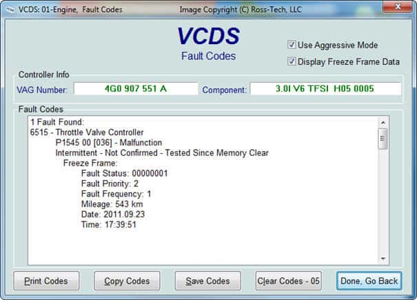
Faults stored in the fault memory do not always have to be active at the time of reading. They can also be faults that have occurred once or several times in the past. Sometimes these faults can be ignored because they were caused, for example, by a low battery voltage, but if the customer complains that the car sometimes hesitates, sometimes starts poorly or sometimes cuts out, then they should be taken seriously. An example of a fault that is currently present can be seen in the image.
The fault is present on the Throttle Valve Controller. That is a translation of the “throttle body”. The fault code is P1545 and it says intermittent. That is English for “occurred sporadically”. It also says Fault Frequency: 1. That means that the fault has only occurred once. The mileage and the date when the fault occurred can also be seen.
When the customer’s complaint is linked to the fault, further investigation into the cause of the fault must be carried out. If the fault were to be cleared, there is a good chance that it would not return, especially if it only occurred once. But there is also a chance that the fault will come back again shortly. The customer therefore cannot simply be sent away after clearing the fault. Clearing does not fix the fault.
Instead of Intermittent, the memory may also show static. In that case, the fault is currently present and cannot be cleared.
If clearing of the fault is attempted anyway, it will almost certainly return immediately.
Controlling actuators:
Another way to locate faults with diagnostic equipment is by controlling actuators.
Actuators are all components that can be controlled; think of a window motor; it is controlled by operating a switch.
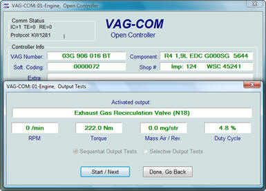
Or an EGR valve in the engine; it is controlled by the ECU to recirculate exhaust gases. With diagnostic equipment these actuators can be controlled manually.
To check the movement of the EGR valve, you do not necessarily have to start the engine and wait until the ECU operates the valve by itself. By operating the diagnostic equipment, the valve can be actuated exactly when the technician needs it.
Actuator diagnostics can also be useful when, for example, the tailgate no longer opens with the tailgate switch. By using the diagnostic equipment to control the tailgate actuator motor, the tailgate is unlocked. If nothing happens when the tailgate switch is operated, the sensor value of the switch can be checked in the live data.
If the value in the live data remains 0 (which means off) instead of 1 (which should appear on the screen during operation), you can conclude that the switch is defective. After all, the tailgate can be operated with the diagnostic equipment.
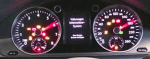
An actuator test can also be carried out on the instrument cluster. During the test, all warning lamps are switched on, all pixels of the maxidot display are activated and all gauges are moved to maximum. Any defects, such as a fuel gauge that does not move further than halfway, will immediately stand out.
Coding, initializing, learning:
After replacing components such as control units, they often need to be coded before they can be put into operation.
The coding consists of a large number of hexadecimal numbers and letters. This can be seen in the image below:
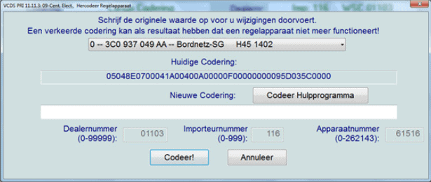
In this case, the Central Electronics control unit is being replaced. When a new control unit is ordered, the software is pre-installed, but it still needs to be told which options the car is equipped with. Of course, there is a difference between a base version without A/C etc. and a fully optioned car with A/C, seat heating, electric windows, etc.
The coding is structured as follows:
05048E0700041A00400A00000F00000000095D035C000
The meanings might be as follows:
First digit: 0 = left-hand drive car, 1 = right-hand drive car.
Second digit: 1 = Australia, 2 = Asia, 3 = South America, 4 = Europe, 5 = North America.
Third digit: 0 = Miles per hour, 1 = Kilometres per hour.
The first three digits therefore indicate that it is a left-hand drive, US-spec car in which miles per hour are displayed. This is apparently pre-programmed as standard during production. Every control unit is supplied with the standard coding. After installation, the control unit must be recoded:
- The second digit (the 5) must be manually changed to a 4 (so from North America to Europe).
- The third digit (the 0) can be manually changed to a 1.
In the car the Dutch language will be set and kilometres will be displayed instead of miles. Every number or letter in the sequence therefore has its own meaning.
Initialization is done in a different way. Often it is sufficient to initialize an electronic component in the car with the press of a button.
Components that need to be initialized include:
- The throttle body, after cleaning or replacement. The ECU must read the values of the throttle position sensors (potentiometers) at fully closed and fully open throttle during the learning process, so that all intermediate values can be determined. If the throttle body is not initialized / adapted, the ECU cannot rotate the throttle to the correct position. The result is that the engine receives too much or too little air at idle and therefore runs poorly at idle. During throttle initialization (in English: Basic settings) the screen will display: “ADP is running”, followed by “ADP OK”. During “running” the throttle is moved to multiple positions and the signal voltage of the potentiometers is monitored. When “ADP OK” appears, the adjustment has been successful.
- The rain sensor after replacement of the windscreen. If the rain sensor has not been properly adapted, the wipers may start wiping too early or too late as soon as raindrops hit the glass;
- The steering angle sensor after work on the steering column;
- The tyre pressure after the tyres have been inflated or replaced;
- Vehicle height after components of the air suspension have been replaced.
- Headlamp height after replacing a headlamp (see image below).
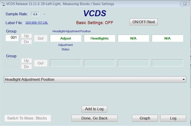
What actually happens during initialization is that the stored values are erased and new (current) values are stored in their place.
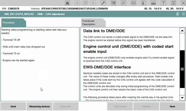
If after repair work on the steering column nothing is done with the initialization of the steering angle sensor, the steering angle sensor may think that the steering wheel is always slightly turned while the vehicle is driving straight ahead. This is detrimental for, among other things, the ESP system. By placing the steering wheel exactly in the straight‑ahead position and giving the diagnostic tool the command to initialize the steering angle sensor, the computer in the car knows the exact point at which the steering wheel is straight ahead. Learning also applies, for example, to the keys. When a new key is purchased, the car cannot simply be started with it. First, the key code must be registered in the car. This is also often done with diagnostic equipment. The key code is stored in the vehicle’s control unit. Only when the key code is recognized by the control unit is the immobilizer deactivated. Only then can the car be started.
Readiness test:
The readiness test is a self-check of the EOBD system. While driving, the EOBD constantly checks the emission-related monitoring functions. The driving cycle must consist of: a cold start, city driving and a stretch of motorway. The vehicle must also be braked to 0 km/h several times and then accelerated again. After this driving cycle, the readiness test can be concluded as “OK” or “not OK”. The readiness test is constantly being carried out by the engine management system.
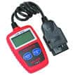
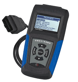
For the periodic inspection (APK) it is mandatory to read out the EOBD in order to check the status of the readiness test and the presence of fault codes. This is allowed with a simple hand‑held tester like the one in the image on the right. It does not need to be brand‑specific and only has the task of displaying the emission‑related fault codes and the readiness test.
During the readiness test, the following items are checked:
- EGR function
- Lambda sensor (operation, ageing, heating)
- Fuel trims (LTFT)
- Catalyst
- Fuel system
- Secondary air system
- Exhaust gas sensor (diesel)
- Diesel particulate filter (diesel)
If, for example, combustion in a cylinder is not correct, or the catalytic converter does not function properly (this is checked with the 2nd lambda sensor, the switching sensor), then the readiness test is stored as “not OK”. A fault code is also stored in the fault memory which can be read with the simple hand‑held tester or other advanced diagnostic equipment.
When the faults are cleared, the readiness test is also cleared. It may therefore take some time before the faults that were erased reappear (if they were not resolved by the repair). Thus it may happen that the fault remains away for a while after clearing and returns later. As soon as the readiness test is complete (after the driving cycle) the fault can be displayed again. After clearing the faults, the readiness test will be displayed as “not OK” in the hand‑held tester. It will take between 10 and 40 km before the new readiness test is stored again.
This also prevents emission‑related faults from being quickly erased before the car is signed off for the APK. The fault code may be gone, but the inspector performing the spot check can then see that the readiness test is not OK.
Standardisation in communication between the diagnostic tester and the car:
With OBD II and EOBD the communication between the diagnostic tester and the vehicle is standardised. A fixed number of service modes is used. These service modes each have their own function. Because it is quite extensive, the table with the general information is given first. Below that follows the detailed explanation…
The table with the different service modes:
| Service 01 | Real‑time data: |
| Parameter identifier indicates which information is available to the diagnostic tester. | |
| Current engine data. | |
| Readiness test. | |
| MIL status (on or off). | |
| Number of stored DTCs (fault codes). | |
| Service 02 | Freeze frame: |
| Request relevant information for when the MIL was lit: At what coolant temperature, engine speed, load, etc.? | |
| Service 03 | Reading DTCs: |
| The P code(s) are displayed. | |
| Service 04 | Clearing diagnostic information: |
| The DTCs, freeze frame and readiness test are erased. | |
| Service 05 | Test values of the lambda sensor: |
| The lambda sensor is continuously checked at ten points to detect deviations caused by ageing or contamination. | |
| Service 06 | Test values of non‑continuously monitored systems: |
| Operation of the catalytic converter. | |
| Service 07 | Test values of continuously monitored systems: |
| Checking for misfires (failing combustion). | |
| Service 08 | Control of systems or components: |
| Checking for air leaks in the tank venting system (US OBDII only). | |
| Service 09 | Requesting vehicle‑specific information: |
| VIN (chassis number). | |
| Service 0A | Permanent fault codes: |
| These cannot be erased with diagnostic equipment, but are erased by the ECU when the conditions are optimal again (e.g. after replacing the catalytic converter). |
The next paragraph provides a detailed explanation of a number of the service modes.
Service modes with the Parameter Identifier:
Service 01:
Here the parameter identifier (PID) is mentioned. The parameter identifier indicates what is supported by the ECU. In the PID the ECU specifies which information it can send to the diagnostic tester. Here is an example:
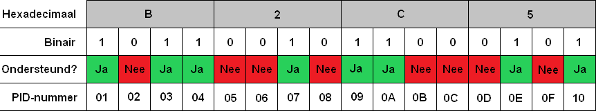
In the CAN protocol, each PID number has its own meaning. PID number 04 could be the coolant temperature. (The exact meaning can be found on the internet). In the table, PID number 04 is listed as Supported: Yes. This is indicated with a 1.
A non‑supported PID number (such as 0B) could, for example, be the exhaust gas temperature sensor on a petrol engine. When this is not present, this will be indicated with a 0.
Ultimately the binary code results in the hexadecimal code. On the page Binary, Decimal and Hexadecimal it is explained in detail how these are converted to one another. The hexadecimal code B2C5 is sent by the ECU to the diagnostic equipment. The diagnostic software recognises which systems are and are not recognised. The systems that are not recognised will be omitted in Service 02.
Service 02:
In service mode 02, the PIDs recorded by the fault code are displayed. These PIDs were determined in service mode 01.
Odometer reading: 35,000 km
Fuel system 1: closed loop
Calculated load: 35
Coolant temperature: 24 °C
Intake air temperature: 18 °C
Engine speed: 2500 rpm
Vehicle speed: 0 km/h
Throttle position sensor: 20%
Frequency: 15
It can be determined that the fault occurred under these conditions. The car was stationary and the throttle was opened until 2500 rpm.
Service 03:
Here the exact fault code is requested. As an example, fault code P0301 is displayed. Code P0301 means: Cylinder 1 has no combustion (misfire detected). The fault codes can be found on the page: OBD Fault codes.
Now that fault P0301 is known, Service 02 is used to check when the fault occurred. It is now known that a misfire occurred in this cylinder under the conditions just described.
Service 0A:
Service 0A contains fault codes that cannot be cleared with diagnostic software. The software in the ECU is programmed in such a way that it calculates itself whether the fault code will be cleared or remain present. As an example we take a diesel particulate filter.
When a particulate filter can no longer be regenerated, it will fill up with soot and become clogged. Before the particulate filter is actually blocked, the backpressure sensors will measure that the backpressure is too high. A fault will be generated. When reading out, the fault P244A (Diesel particulate filter: Pressure difference too high) will be displayed. The difference between the two backpressure sensors (before and after the filter) is too great, which means that the particulate filter is saturated (i.e. full of soot).
This fault cannot be cleared. Two options remain:
- Regenerate the particulate filter;
- If regeneration is not possible: replace the particulate filter.
After the repair, the fault will remain stored in memory. While driving, the readiness test will show that the backpressure differences are now minimal. The software now recognises that the particulate filter is no longer clogged. The ECU will now clear the fault itself.
This does not apply only to the particulate filter; it will work in the same way for a catalytic converter with poor efficiency.
The remaining service modes (04 to 09) have already been described in quite some detail in the table, so they will not be discussed further here.